
Propeller and method in which a propeller is set into motion

a propeller and propeller technology, applied in the field of propeller and propeller setting into motion, can solve the problems of difficult to obtain propulsion in viscoelastic media with existing devices, many important tissues in the biomedical domain are neither pure, and achieve the effect of easy and reliable manufacture of propellers

Active Publication Date: 2020-01-30
MAX PLANCK GESELLSCHAFT ZUR FOERDERUNG DER WISSENSCHAFTEN EV
View PDF0 Cites 0 Cited by
  • Summary
  • Abstract
  • Description
  • Claims
  • Application Information

AI Technical Summary

Benefits of technology

The invention relates to a propeller for a device that moves through biological tissue. The surface of the propeller is smooth to prevent the adhesion of the tissue and to minimize the resistance to movement. The material of the propeller is metal, anti-adhesion polymer, or biocompatible polymer, and a coating can be applied to further reduce adhesion. The actuation methods induce large shear on the surface to reduce adhesion. The propeller has a forward taper to decrease the area of contact with the medium. The manufacturing method involves twisting a plate into helical shape and cutting it into individual propellers. The technical effects of the invention include reducing the adhesion of medium to the propeller, minimizing the resistance to movement, and improving the efficiency of the device.

Problems solved by technology

It can be challenging to further miniaturise existing devices.
Moreover, it has proven difficult to obtain propulsion in viscoelastic media with existing devices.
However, many important tissues in the biomedical domain are neither purely viscous fluids nor purely elastic solids.
The inventors have found that the known propeller shapes can be inefficient in viscoelastic media.

Method used


Image

  • Propeller and method in which a propeller is set into motion
  • Propeller and method in which a propeller is set into motion
  • Propeller and method in which a propeller is set into motion

Examples


Embodiment Construction

[0023]Further preferred features of the invention which may be applied alone or in combination are discussed in the dependent claims, description below and the figures.

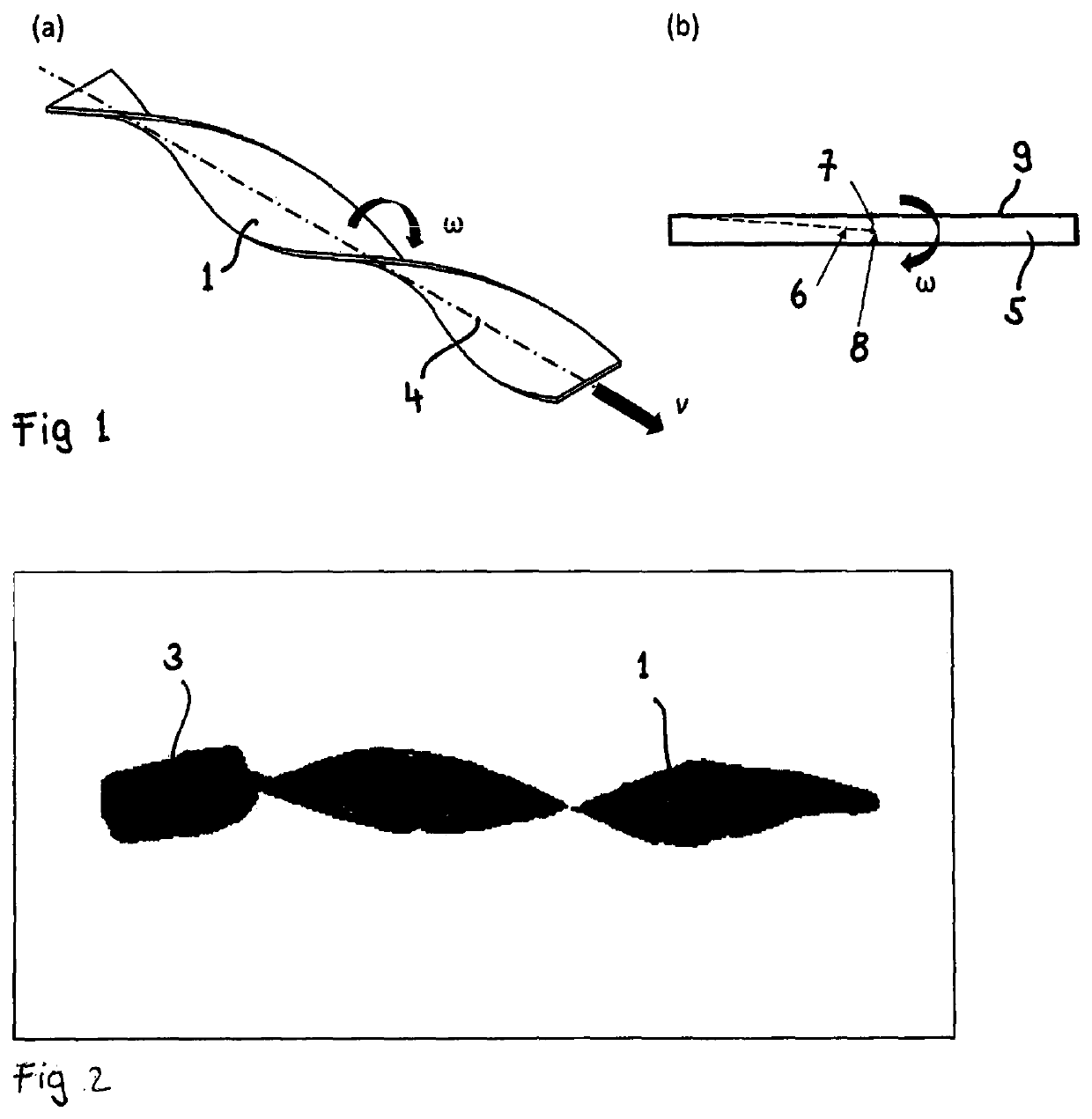
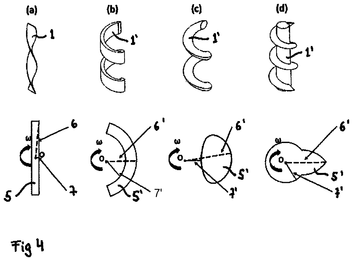
[0024]In a preferred embodiment of the invention, the aspect ratio of at least one cross section, preferably all cross sections, of the propeller, is / are 2 or more, more preferably 3 or more, more preferably 5 or more, more preferably 10 or more, more preferably 20 or more, more preferably 50 or more, more preferably 100 or more; the cross section(s) are related to the propeller's rotational axis or, alternatively, to the propeller's helical axis. This embodiment of the invention exploits the inventors' finding that a particularly high aspect ratio can entail a particularly strong propulsion. The cross section preferably is of a continuous shape.

[0025]Preferably, at least one cross section, more preferably every cross-section, of the propeller related to the propeller's rotational axis has a cross-sectional area that ...


PUM


Abstract

A method where a propeller is set into locomotion relative to a medium at least partially surrounding the propeller. An actuator induces a rotation of the propeller relative to the medium and about a rotational axis of the propeller, and the propeller converts its rotational movement into locomotion relative to the medium. The aspect ratio of at least one cross-section of the propeller is three or more. Also a helical or modifiedly helical propeller for converting rotational movement of the propeller into locomotion of the propeller relative to a medium at least partially surrounding the propeller, where the aspect ratio of at least one cross section of the propeller is three or more. And a method of producing a propeller, including the step of providing a plate extending along the helical axis, where the aspect ratio of at least one cross section of the plate is three or more.

Description

FIELD OF THE INVENTION[0001]The invention concerns a method in which a propeller is set into locomotion relative to a medium which at least partially surrounds the propeller, wherein an actuator induces a rotation of the propeller relative to the medium and about a rotational axis of the propeller, and wherein the propeller converts its rotational movement into locomotion of the propeller relative to the medium. It moreover concerns a helical or modifiedly helical propeller for converting rotational movement of the propeller into locomotion of the propeller relative to the medium. Furthermore, the invention concerns methods of producing the propeller.BACKGROUND OF THE INVENTION[0002]In many applications in medicine and biology it can be of advantage to be able to penetrate biological media, including biological fluids and soft tissues. For example, in minimally invasive procedures, such as the targeted delivery of substances or minimally invasive surgical procedures, it can be desir...

Claims


Application Information

Patent Timeline
IPC IPC(8): B26D5/08B26D1/00
CPCA61B34/73B26D1/0006A61B2017/320775B26D5/086B26D2001/0073A61B17/00A61B17/320758A61B2034/303A61B2017/00345A61B2017/00411
Inventor QUI, TIANFISCHER, PEER
Owner MAX PLANCK GESELLSCHAFT ZUR FOERDERUNG DER WISSENSCHAFTEN EV
Learn More