
Cushioning member and method of manufacturing the same

Inactive Publication Date: 2006-03-09
TSUCHIYA TSCO CO LTD +1
View PDF8 Cites 5 Cited by
  • Summary
  • Abstract
  • Description
  • Claims
  • Application Information

AI Technical Summary

Benefits of technology

[0007] It is an object of the present invention to provide a cushioning member that performs a satisfactory cushioning function.
[0008] It is another object of the present invention to provide a method of manufacturing a cushioning member, which is capable of easily and reliably manufacturing the cushioning member comprised of a pair of base members and pile yarns bridging between the base members.

Problems solved by technology

However, when the shutter curtain is moved in lateral directions, the sliding element following the motion is pulled by mohair located on opposite lateral sides with respect to the direction of motion thereof, which makes the sliding element difficult to move, and which prevents the cushioning function from being fully performed.
Whichever method may be employed, it is required to once form the mohair member, and hence the manufacturing process is complicated.
Furthermore, since the mohair is flexible, it is difficult to bond the mohair only by mohair ends, or aligning them, which makes it very difficult to manufacture the silencing band body.

Method used


Image

  • Cushioning member and method of manufacturing the same
  • Cushioning member and method of manufacturing the same
  • Cushioning member and method of manufacturing the same

Examples


Embodiment Construction

[0037] Hereinafter, a first embodiment of the present invention will be described with reference to the drawings.

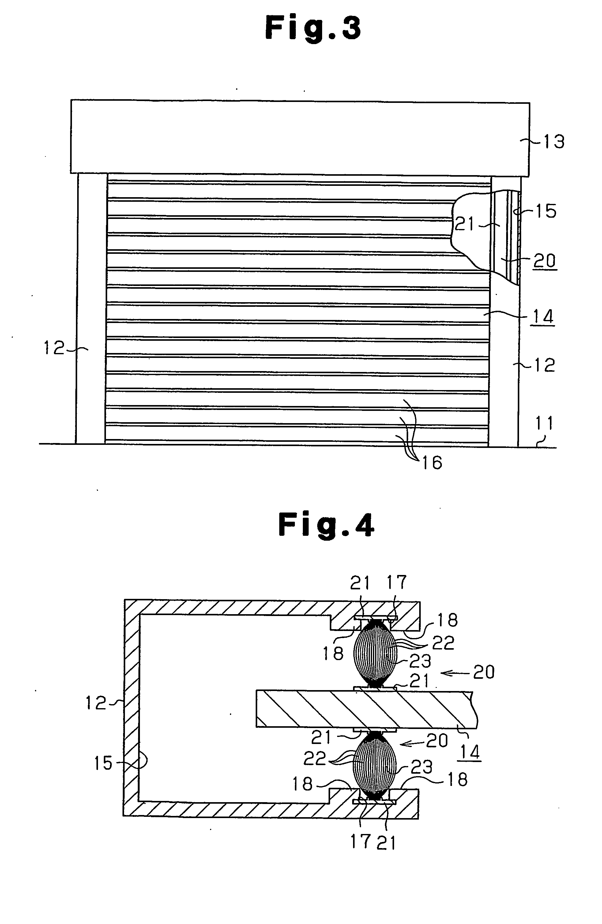
[0038] First, a description will be given of the construction of a shutter apparatus that uses cushioning members for a shutter apparatus. As shown in FIGS. 3 to 5, the shutter apparatus is comprised of a pair of support frames 12 set upright on a floor 11 in a manner opposed to each other, a housing 13 bridging between upper ends of the support frames 12, and a shutter 14 disposed inside the floor 11, the pair of support frames 12, and the housing 13. The support frames 12 function as guiding members. The shutter 14, which functions as a moving member, is formed by joining a plurality of vane plates 16 such that the vane plates 16 pivot relative to each other. The shutter 14 can be wound round in a spiral manner by pivotally moving each vane plate 16. Further, inside the housing 13, a hollow cylindrical drum, not shown, is rotatably supported, and an upper end of the sh...


PUM

PropertyMeasurementUnit
Lengthaaaaaaaaaa
Electrical resistanceaaaaaaaaaa
Shapeaaaaaaaaaa

Abstract

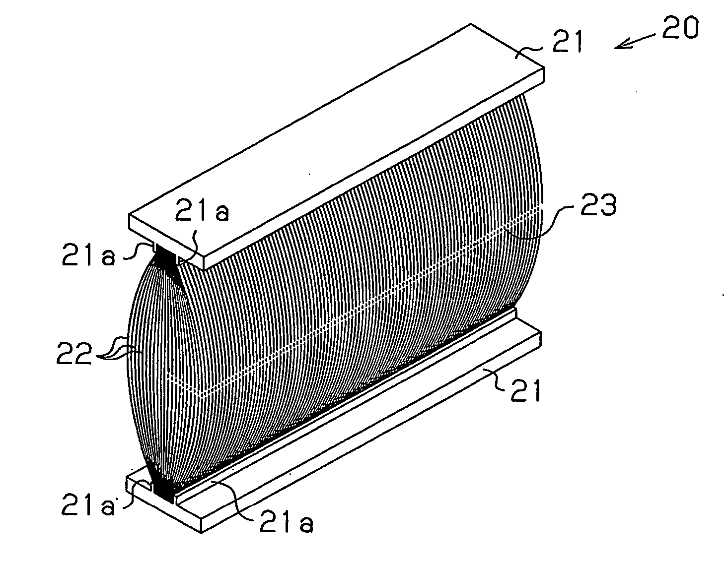
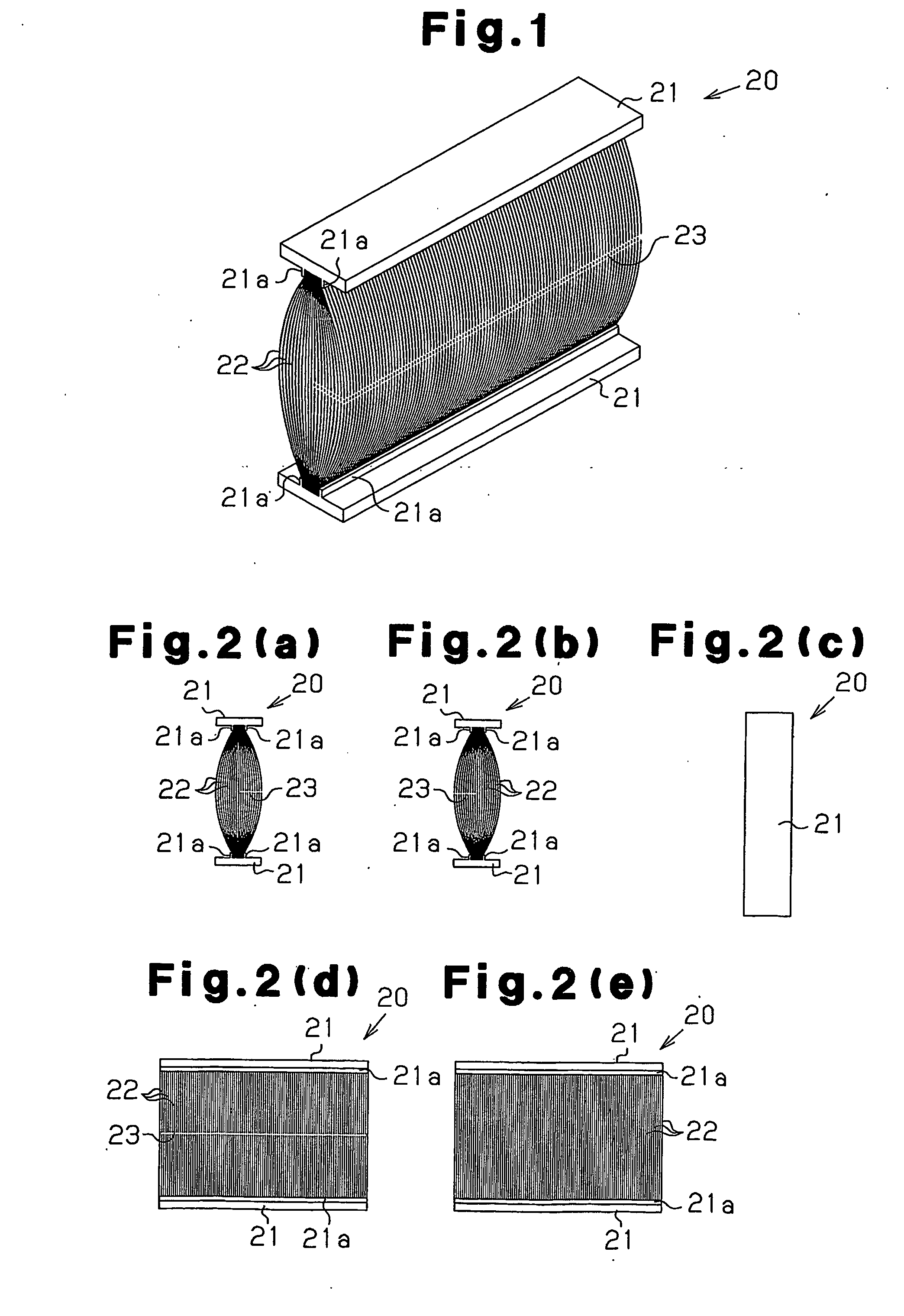
A cushioning member is located between each support frame and the corresponding side of the shutter. The cushioning member includes a pair of belt-shaped base members and pile yarns bridging between the base members. Some of the pile yarns are cut at intermediate portion between the base members, which forms opposing first and second cut pile yarns with a cut in between. One of the base members is attached to each support frame, and the other base member contacts the shutter. The cut permits the cushioning member to flexibly respond to movements of the shutter and satisfactorily exerts a cushioning function to suppress swaying of the shutter.

Description

TECHNICAL FIELD [0001] The present invention relates to a cushioning member and a method for manufacturing the cushioning member. For example, the present invention relates to a cushioning member for a shutter apparatus including a pair of opposed support frames and a shutter for moving between the support frames, the cushioning member being interposed between the support frames and opposite sides of the shutter. BACKGROUND ART [0002] Conventionally, as disclosed in Japanese Utility Model Registration No. 2592349, a silencing band structure has been proposed as a cushioning member for the shutter apparatus of the above-mentioned kind. More specifically, a silencing band body according to this silencing band structure includes a band-shaped sliding element and a band-shaped base, which are both formed of a hard material, such as hard vinyl chloride. The sliding element and the base are bridged with mohair such that the components of the sliding element, the base, and the mohair are i...

Claims


Application Information

Patent Timeline
IPC IPC(8): F16F1/36
CPCF16F7/00E06B9/582
Inventor OHARA, YASUYUKITAKAMI, HAJIMEKAWASHITA, TAKASHIWYLIE, GRANT
Owner TSUCHIYA TSCO CO LTD
Learn More