
Voltage reference circuit, voltage detector and voltage detector system

Active Publication Date: 2020-01-23
UNIVERSITY OF BRISTOL
View PDF3 Cites 5 Cited by
  • Summary
  • Abstract
  • Description
  • Claims
  • Application Information

AI Technical Summary

Benefits of technology

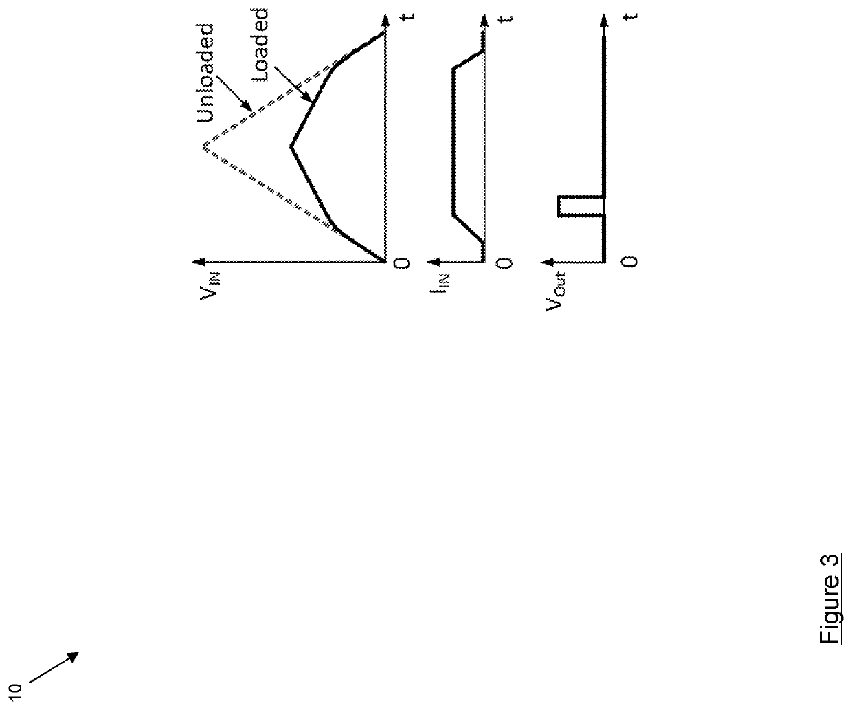
The patent describes a structure that allows a voltage reference to be generated with low current consumption. It also describes how the detector can be turned off when no longer needed, saving current. The reduction of the reference voltage can help reduce current leakage. Buffers can be added to sharpen the detector's response. The system has a steady quiescent current that enables continuous monitoring of the output of sources with high impedance. It also has a low threshold voltage, allowing it to capture as many power-containing pulses as possible, and a high maximum input voltage, ensuring capture of higher power pulses without sustaining damage. The leakage current from or into the detector is minimal.

Problems solved by technology

For example, if the wearer of the device rests in a position such that a power receiving antenna is poorly oriented relative to the transmitter, then an input power lull occurs.
This problem of intermittency occurs with the majority of energy generation and wireless power transfer techniques, and is only exacerbated when some of the system is situated on a moving body.
In practice, however, existing commercially-available voltage detectors have a significant input quiescent current, especially once activated.
For these sources, input monitoring and input-dependent power gating is therefore not currently possible.
However, the output is a short reset-pulse, which does not provide information on the duration of the incoming source power.
Additional protection circuits could be used to protect the circuit from potentially damaging over voltage conditions, but by clamping the input voltage at 4V, a significant percentage of the source power would be lost.
The technology used permits detection thresholds of a few hundred mV, but this also reduces the maximum allowed input voltage.
The detection threshold, however, is 3.6 V, which is too high for many applications.
However, its maximum input voltage is 0.1 V, which is too low for many applications.
As will be appreciated from the discussion above, existing commercial discrete voltage detectors and integrated detection circuits are unsuitable for the continuous, non-invasive monitoring of high-impedance source voltages.

Method used


Image

  • Voltage reference circuit, voltage detector and voltage detector system
  • Voltage reference circuit, voltage detector and voltage detector system
  • Voltage reference circuit, voltage detector and voltage detector system

Examples


Embodiment Construction

[0086]FIG. 5 illustrates a voltage detection system which combines all the desired properties of voltage detectors, namely high maximum input voltage, a low voltage detection threshold and low quiescent power consumption. The system, shown generally at 100 in FIG. 5, includes a power gating stage 120, a voltage detection stage 140 and an output stage 160.

[0087]The voltage detection stage 140 includes a first voltage detector 142 which is configured to detect input voltages in a high voltage range (e.g. in the range 2.8 volts to 20 volts), a second voltage detector 144 which is configured to detect input voltages in a medium voltage range (e.g. 0.6 volts to 2.8 volts) and a third voltage detector 146 which is configured to detect input voltages in a low voltage range (e.g. 0.45 volts to 0.6 volts). This arrangement of three voltage detectors ensures that the voltage detection system 100 is able to operate in a wide input voltage range, therefore facilitating the capture of energy fro...


PUM


Abstract

A voltage detector (200) for monitoring an input signal and outputting a detection signal at an output when a voltage of the input signal meets a first threshold having: an input configured for receiving the input signal; a voltage reference circuit for receiving an input voltage and producing a reference voltage having a maximum value independent of the input voltage; and a trigger configured to compare the input signal and the reference voltage and to output a detection signal to the output when the voltage of the input signal reaches the first threshold. The voltage reference circuit comprises a reset input connected to either the input or the output and is configured to reduce the reference voltage when a predetermined reset signal is received. The voltage reference circuit may include: an input for receiving the input voltage; a first current controlling element (210), such as a diode, which allows current to flow as an increasing, non-linear function of voltage at least within a first range of voltages; a second current controlling element (240), such as a transistor, which allows current to flow as an increasing, non-linear function of voltage at least with a second range of voltages; and an output at which the output reference voltage is produced. The first current controlling element and the second current controlling element are connected in series between the input and a common reference, with the second current controlling element between the first current controlling element and a common reference, the output comprises a node between the two current controlling elements, the first and second range of voltages overlap and the second current controlling element is configured to vary the function by which it allows current to flow in dependence on the input voltage.

Description

TECHNICAL FIELD[0001]The present application relates to a voltage reference circuit, a voltage detector and a voltage detector system.BACKGROUND TO THE INVENTION[0002]Voltage reference circuits find application as part of a wide range of electronic circuits including sensing, comparison, low voltage logic and op amp circuits and Schmidt triggers.[0003]In the context of sensing, sensors such as those used in medical devices can be powered by wireless power transfer or energy harvesting sources. In the case of sensors that are worn on the human body, these sources provide intermittent power due to the body's movement. For example, if the wearer of the device rests in a position such that a power receiving antenna is poorly oriented relative to the transmitter, then an input power lull occurs. This problem of intermittency occurs with the majority of energy generation and wireless power transfer techniques, and is only exacerbated when some of the system is situated on a moving body.[0...

Claims


Application Information

Patent Timeline
IPC IPC(8): G01R19/165H03K17/22G05F3/24
CPCG05F3/24H03K17/223G01R19/16538G01R19/16576G01R15/04G05F3/10G01R19/16519
Inventor ADAMI, SALAHPROYNOV, PLAMENSTARK, BERNARDYANG, GUANGZHANG, CHUNHONG
Owner UNIVERSITY OF BRISTOL
Learn More