Fabrication and design of composites with architected layers
a technology of architected layers and composite materials, applied in the field of composite material systems, can solve the problems of affecting the absorption and/or damping behavior, unobtainable or otherwise difficult to obtain in the conventional material system, and achieve the effect of increasing adhesion
- Summary
- Abstract
- Description
- Claims
- Application Information
AI Technical Summary
Benefits of technology
Problems solved by technology
Method used
Image
Examples
example 1
sponse of 3D Carbon Architectures
[0183]Fabrication and design of materials with high stiffness- or strength-to-density ratios has been studied through the use of cellular materials. In particular, beam-based lattice architectures have enabled the creation of lightweight-but-stiff materials (1; 2) as well as strong materials that approach theoretical bounds (3). Many of these studies have focused on the static response of these materials, while few works have studied the dynamic response of lattice architectures. In particular, some works have studied the dynamic compression of lattice structures at the μm-scale (4), while others have studied the impact of macro-scale structures such as lattice-core sandwich plates (5). Due to the length scales and tessellations associated with these studies, neither achieves proper separation of scales in which the length-scale of the boundary conditions is much greater than that of the inherent microstructure. Such separation would allow probing of...
example 2
Damping Through Architecture
[0203]Careful design of architected materials can lead to interesting dispersive behavior, which can translate to energetic dissipation. Works have shown large 3D-printed effective materials that can dampen vibrations (10) as well as micro-scale materials that dissipate ultrasonic waves in water (11), through the use of dispersion mechanisms such as Bragg scattering and local resonance. Proper design of architecture, while accounting for material density and stiffness, can lead to effective material damping with stiff, non-dissipative constituent materials.
[0204]In the present Example, we utilize careful design of architecture to take advantage of Bragg scattering and local resonance mechanisms to dissipate vibrational energy with stiff, non-damping constituent materials.
[0205]2.1 Bragg Scattering: Tetragonal Lattice
[0206]Starting with a tetragonal unit cell such as the one depicted in FIG. 18A, volumetric expansion of its members would result in buckling...
example 3
able Elasticity Through Spinodal Decomposition-Derived Architectures
[0222]Architected materials with beam-based architectures have been shown to be effective in achieving high stiffness-to-density ratios (1; 6), but they still fall short from the theoretical bounds. Additionally, their mechanical properties deviate from the theoretical predictions due to the existence of nodes (7), which also serve as stress concentrations that can lead to failure.
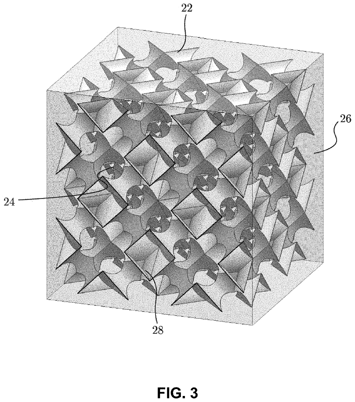
[0223]In this Example, we describe the use of spinodal decomposition to create shell-based microstructures that lack nodes and achieve superior mechanical properties and higher mechanical tunability than beam-based architectures.
[0224]3.1 Elastic Surface Tunability
[0225]Using spectral methods and an anisotropic energy functional (13), numerical spinodal decomposition can lead to microstructures with fully tunable elasticity. (For exemplary methods describing computational spinodal decomposition, see: A. Vidyasagar, S. Krodel, and D. M. Koc...
PUM
| Property | Measurement | Unit |
|---|---|---|
| Fraction | aaaaa | aaaaa |
| Fraction | aaaaa | aaaaa |
| Fraction | aaaaa | aaaaa |
Abstract
Description
Claims
Application Information
 - R&D
- Intellectual Property
- Life Sciences
- Materials
- Tech Scout
- Unparalleled Data Quality
- Higher Quality Content
- 60% Fewer Hallucinations
Browse by: Latest US Patents, China's latest patents, Technical Efficacy Thesaurus, Application Domain, Technology Topic, Popular Technical Reports.
© 2025 PatSnap. All rights reserved.Legal|Privacy policy|Modern Slavery Act Transparency Statement|Sitemap|About US| Contact US: help@patsnap.com


