Vane cutting apparatus

Inactive Publication Date: 2019-12-19
DURO DYNE CORP
View PDF0 Cites 0 Cited by
  • Summary
  • Abstract
  • Description
  • Claims
  • Application Information

AI Technical Summary

Benefits of technology

The apparatus and method described in this patent use a pneumatically powered cutting mechanism to perform hollow turning vane cutting. This allows for a smaller apparatus footprint with no loss of cutting force, resulting in a single stepped blade rolling the inside edges of the hollow turning vane during cutting. The apparatus includes a 110 volt source controlled by an on / off toggle switch, and an operator safety mechanism to ensure operator safety. Additionally, the apparatus uses a reversible single stepped cutting blade that is resharpenable and provides a longer life of the blade function during production. These technical effects enhance the performance and efficiency of the cutting process.

Problems solved by technology

Cutting hollow turning vanes in this manner often leads to a distortion of the exposed cut vane edges and the possibility of an unsmooth surface that may not be at a ninety degree angle to the vane.
Along with the potential for decreased quality, using the abrasive cut-off saw may also increase the time of production, cost of labor, and in some cases reduced safety for the cutting operator.

Method used


Image

  • Vane cutting apparatus
  • Vane cutting apparatus
  • Vane cutting apparatus

Examples


Embodiment Construction

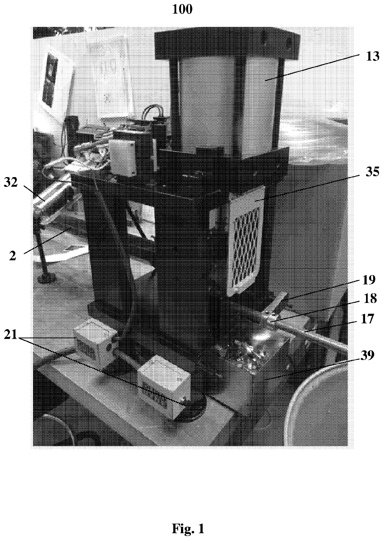
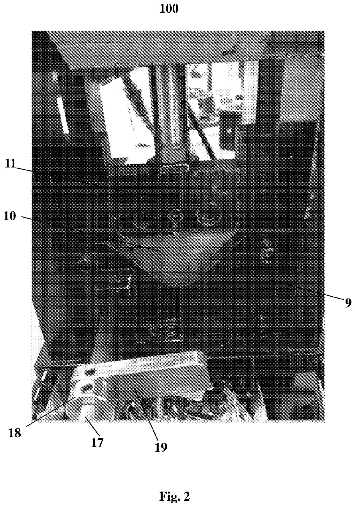
[0048]With reference now to FIGS. 1 and 2, a hollow turning vane cutting apparatus 100 is disclosed. Vane cutting apparatus 100 is configured for cutting hollow turning vanes for use in HVAC systems. Vane cutting apparatus 100 may be configured, for example, to cut 2″, 4″, or any other size hollow turning vanes. Vane cutting apparatus 100 is configured to cut the hollow turning vanes to a desired length for use in an HVAC system.

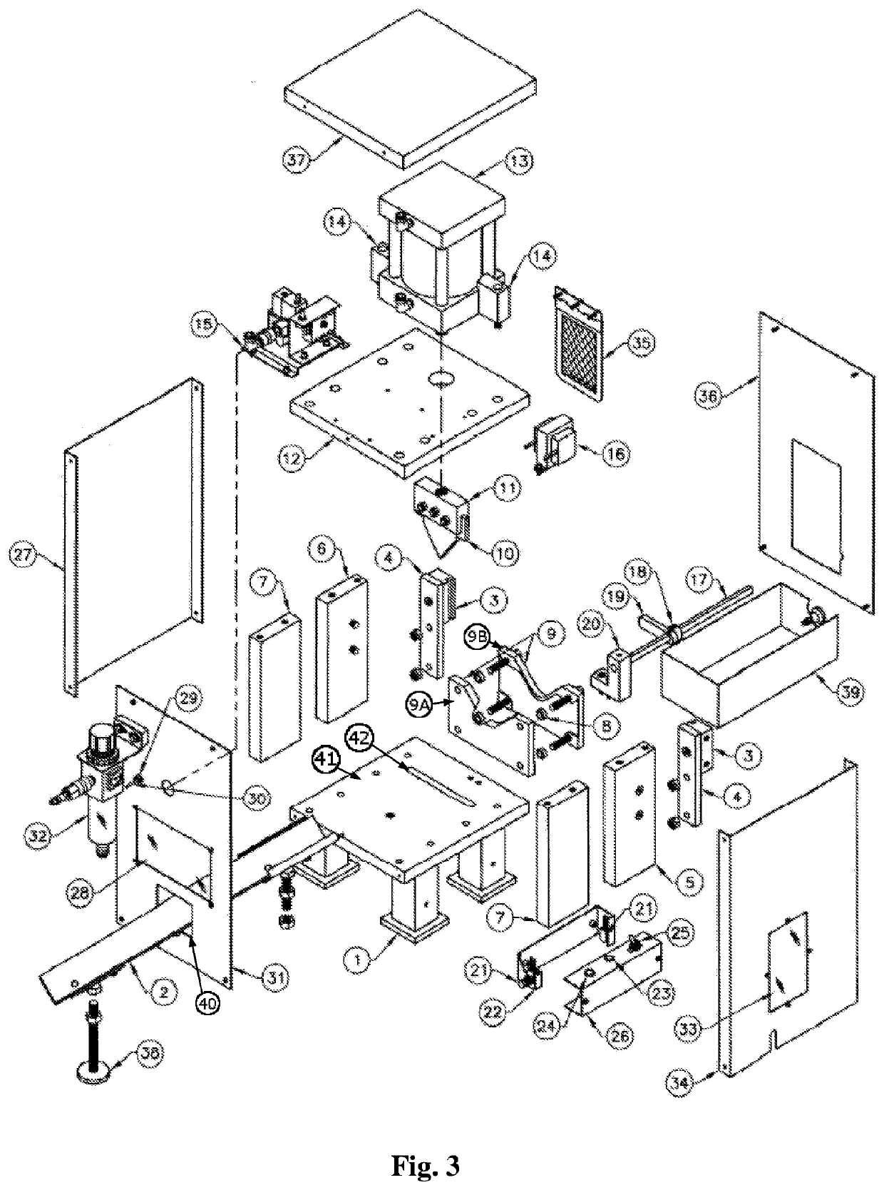
[0049]With reference now to FIG. 3, aspects of vane cutting apparatus 100 will now be disclosed. In some aspects, vane cutting apparatus may include any or all of the following components as illustrated in FIG. 3:[0050]1)—Lower Plate Leg Weldment[0051]2)—Material Feed Track Assembly[0052]3)—Top Blade Guide[0053]4)—Blade Support Block[0054]5)—Upright Support with Mounting Holes-Control Side[0055]6)—Upright Support with Mounting Holes-Non Control Side[0056]7)—Upright Support[0057]8)—Saddle Spacer[0058]9)—2″ / 4″ Blade Saddle[0059]9A)—First portion of blade saddl...


PUM

PropertyMeasurementUnit
Lengthaaaaaaaaaa
Forceaaaaaaaaaa
Angleaaaaaaaaaa

Abstract

The present disclosure relates to apparatus and methods for cutting a hollow turning vane to a desired length for use in a heating, ventilation, and air conditioning (HVAC) system. The vane cutting apparatus disclosed herein utilizes a pneumatically powered cutting mechanism that allows for a smaller apparatus footprint with no loss of cutting force and results in the single stepped blade rolling the inside edges of the hollow turning vane during cutting. The rolled inside edges provide a more secure and smoother fit when the hollow turning vane is fastened to the mating vane rail for use in an HVAC duct.

Description

FIELD[0001]The present disclosure relates to apparatus and methods for cutting a hollow turning vane to a desired length for use in a heating, ventilation, and air conditioning (HVAC) system.BACKGROUND[0002]Hollow turning vanes are used in the ductwork of HVAC systems to smoothly direct airflow when there is a change in direction, for example, around an intersection or corner in the ductwork.[0003]In the HVAC industry, cutting hollow turning vanes to a size for use in ductwork often includes the use of a hand or powered abrasive cut-off saw. Cutting hollow turning vanes in this manner often leads to a distortion of the exposed cut vane edges and the possibility of an unsmooth surface that may not be at a ninety degree angle to the vane. Along with the potential for decreased quality, using the abrasive cut-off saw may also increase the time of production, cost of labor, and in some cases reduced safety for the cutting operator.BRIEF SUMMARY[0004]The apparatus and method described he...

Claims


Application Information

Patent Timeline
IPC IPC(8): B23D23/00B23D15/04B23D15/14B23D33/10B23D33/12
CPCB23D23/00B23D33/12B23D15/04B23D33/10B23D15/14B26D1/08B26D3/16B26D5/12B26D2007/013B23D25/00
Inventor BELLISE, ANDREW J.SMITH, AINSLEY F.KRUPNICK, DAVID B.
Owner DURO DYNE CORP
Why Eureka
Try Eureka