
Illumination system and projection apparatus

a technology of projection apparatus and projection system, which is applied in the direction of picture reproducers, picture reproducers using projection devices, instruments, etc., can solve the problems of reducing the lighting efficiency of light emitting diodes, generating more heat, and limited heat dissipation ability, so as to reduce heat resistance and increase heat dissipation efficiency

Inactive Publication Date: 2019-11-07
YOUNG OPTICS
View PDF7 Cites 1 Cited by
  • Summary
  • Abstract
  • Description
  • Claims
  • Application Information

AI Technical Summary

Benefits of technology

The present invention is an illumination system that uses a thermoelectric cooler (TEC) to improve heat dissipation efficiency. The TEC helps to reduce the heat resistance between light emitting diodes and the atmosphere, making it easier for the system to remove the heat that is generated during use. This results in improved performance and reliability of the illumination system.

Problems solved by technology

However, the high-powered light emitting diodes generate more heat, and the heat reduces lighting efficiency of the light emitting diode source.
However, even if the heat dissipation fins are mounted to the light emitting diodes, heat resistance between the light emitting diode and air is not eliminated completely, which results in limited heat dissipation ability.

Method used


Image

  • Illumination system and projection apparatus
  • Illumination system and projection apparatus
  • Illumination system and projection apparatus

Examples


Embodiment Construction

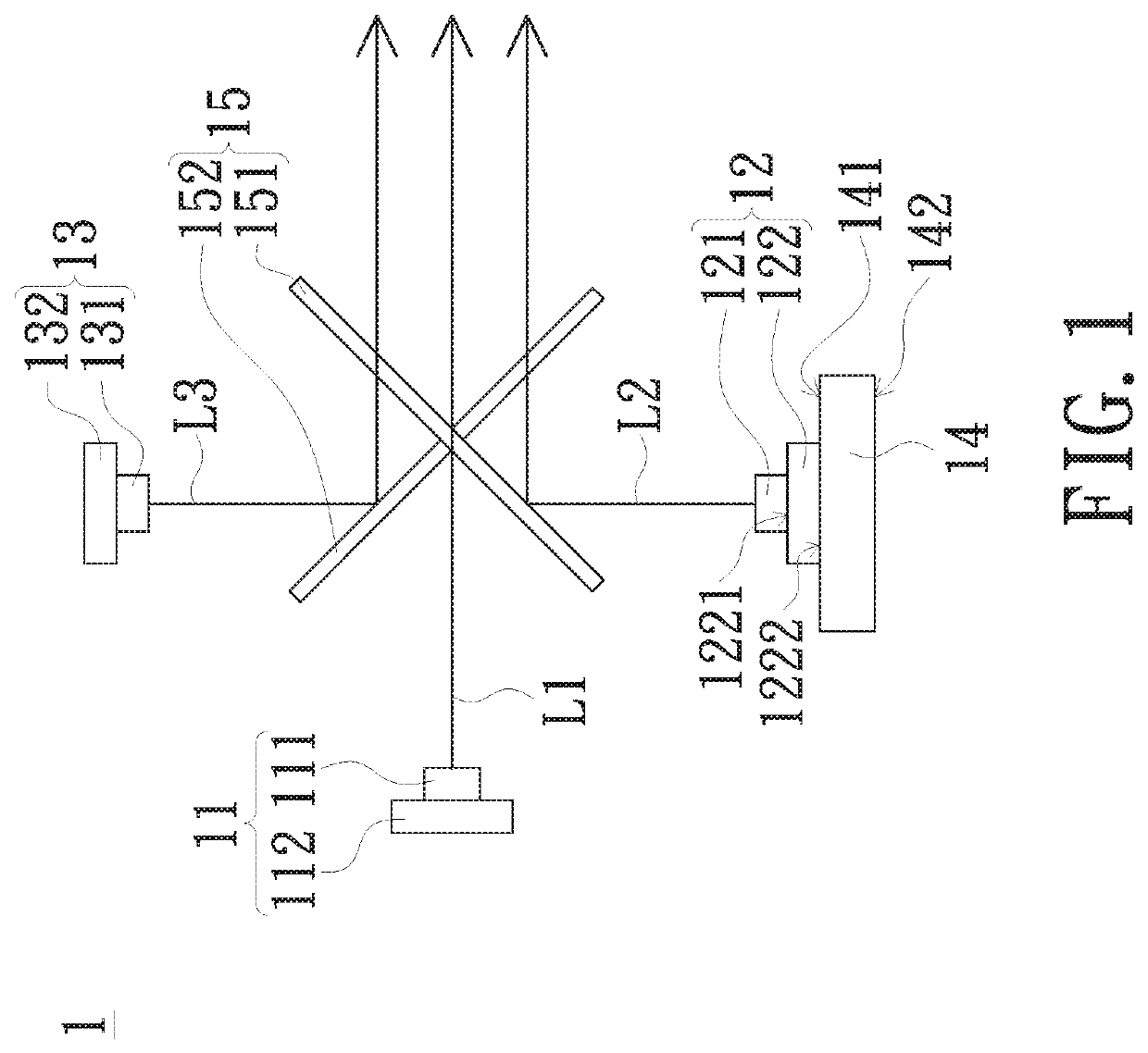
[0013]These embodiments refer to use “first”, “second”, etc. following with noun or element. Such terms should be understood as a nomenclature and should not be construed as giving the limitation on the number of the elements modified by such nomenclature unless a specific number has been given. Optical elements of the invention refer to an element partially or totally made of reflective or transparent material which usually includes glass or plastic. Light beam combination of the invention refers to a combination of more than one light beam into one light beam. “Element A thermally coupled to element B” of the invention refers to the element A and the element B has thermal conductive relation. For example, if the heat of the element A is transferred to element B via a thermal material layer such as thermal grease, then the element A and the element B are thermally coupled.

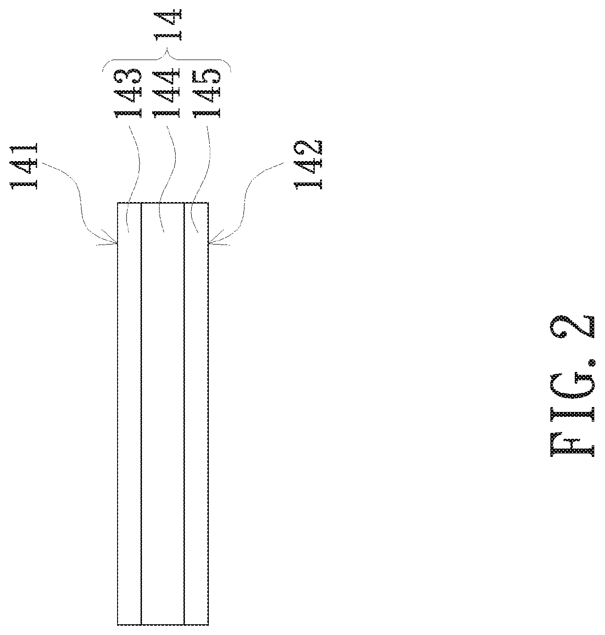
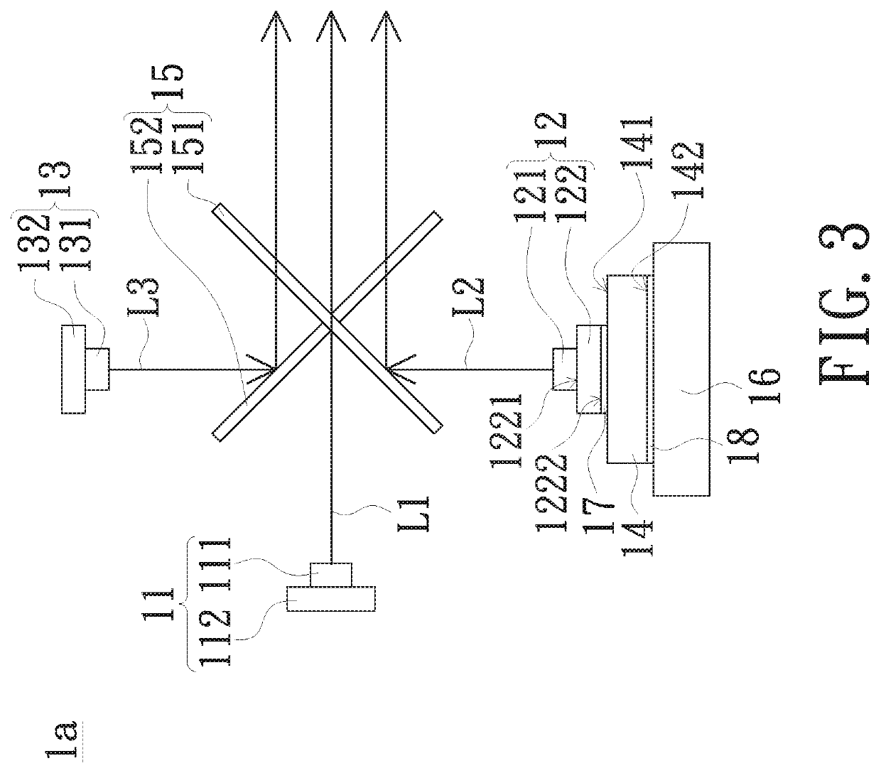
[0014]FIG. 1 is a schematic diagram of an embodiment of an illumination system of the present invention. Referr...


PUM


Abstract

An illumination system includes a green light source, a red light source, a blue light source, a first splitter, a second splitter, and a thermoelectric cooler. The first splitter is disposed downstream of the light sources, the first splitter being capable of reflecting a first color light beam and allowing a second color light beam to pass. The second splitter is disposed at the light paths of the light sources, and the second splitter being capable of reflecting a third color light beam and allowing the first color light beam and the second color light beam to pass, wherein the color of the first color light beam, the second color light beam, and the third color light beam are substantially different. The thermoelectric cooler is thermally coupled to the red light source, and neither the green light source nor the blue light source is thermally couple to any thermoelectric cooler.

Description

CROSS-REFERENCE TO RELATED APPLICATIONS[0001]This is a continuation application of prior application Ser. No. 15 / 928,146 filed on Mar. 22, 2018.FIELD OF THE INVENTION[0002]The present invention relates to an illumination system and a projection apparatus, and more particularly to an illumination system and a projection apparatus provided with an enhanced heat dissipation structure.BACKGROUND OF THE INVENTION[0003]As the light emitting diode source become popular, more projection apparatuses utilize light emitting diode (LED) as the light sources thereof. To satisfy the requirement of high luminous intensity, high-powered light emitting diodes are used as the light source. However, the high-powered light emitting diodes generate more heat, and the heat reduces lighting efficiency of the light emitting diode source. Therefore, in the conventional projection apparatuses, heat dissipation fins are often mounted to the light emitting diodes to improve heat dissipation efficiency. However...

Claims


Application Information

Patent Timeline
Patent Type & Authority Applications(United States)
IPC IPC(8): G03B21/16G03B21/20G03B33/08G03B33/12H04N9/31G02B27/14H05K1/02H10N10/13
CPCG03B33/08H05K1/181H04N9/3164G03B21/16H05K2201/10174H05K2201/10121G03B21/2013G02B27/14H04N9/3111G03B21/2033H04N9/3144G02B27/149G03B21/2066H05K1/0203H01L35/30H05K2201/10106G03B33/12H10N10/13
Inventor HUANG, JIA-BIN
Owner YOUNG OPTICS
Learn More