X-ray imaging systems and methods, and methods of manufacture of collimators for use therein

Active Publication Date: 2019-09-26
ROLLS ROYCE PLC
View PDF2 Cites 6 Cited by
  • Summary
  • Abstract
  • Description
  • Claims
  • Application Information

AI Technical Summary

Benefits of technology

The patent text describes a method for using an X-ray imaging apparatus to create detailed images of objects. The apparatus uses a collimator and a detector to capture the X-rays that pass through the collimator and the object being imaged. The image data from each sensor is then combined to create the final image. The method also involves filling the channels of the collimator to improve its performance and mechanical properties. The technical effect of this invention is to provide a more efficient and accurate method for X-ray imaging.

Problems solved by technology

Geometric unsharpness is a known problem in many x-ray imaging systems, due to the fact that the x-rays typically originate from a source of finite size, rather than from a point source.
Often, source to object distance and object to detector distance are limited by external factors such as geometry of the object to be imaged.
However, using a small spot size is often not possible, especially in high power x-ray systems.
If heat is not dissipated effectively, this can cause damage to the x-ray source, for example, by melting of the target material (typically e.g. tungsten).
However, sizes smaller than this are typically not achievable for the reasons mentioned above.
Additionally, such focused source systems can suffer from problems of reduced image brightness (due to lower maximum energy), and reduced reliability (for example, requiring a shorter service interval) in comparison to typical sealed tube x-ray sources.
Furthermore, the scan rate with such ‘micro-focus’ sources can be slow, and the systems can also be expensive and complex in comparison to typical ‘unfocussed’ x-ray imaging systems.
Another problem common in x-ray imaging systems is reduced contrast in the resultant image due to noise from scattered x-rays reaching the detector.
This is particularly a problem for imaging of large structures (e.g. large aero engine components).
However, such collimators can significantly reduce brightness of the image formed, and also do not assist in overcoming the problem of geometric sharpness.
However, this is generally not possible in most known x-ray imaging systems without significantly decreasing the image quality due to increased geometric unsharpness, for the reasons as discussed above.
However, such production methods have difficulty in producing collimators having complex or fine geometry, which may be useful for certain x-radiographic techniques.
Whilst some work has been done on producing collimators with complex or fine geometry using additive manufacturing processes, challenges arise where it is desired to produce very fine holes, or holes having a high aspect ratio.
In particular, some problems which current methods suffer from include:Minimum width of ligament walls greater than desired (ligament walls being internal walls between channels of the collimator), leading to reduced image brightness;Unsatisfactory roughness of collimator channels / ligament walls;Adherent, partially bonded particles within collimator channels which may obstruct ray paths; andEntrapped powder within collimator channels, particularly where the channel arrays are not parallel and vertical in the build orientation.
However, the fabrication costs may be higher for a production of a higher-density collimator body.
Whilst increasing the number of x-ray sources may be beneficial to ensure full coverage of the x-ray source side of the channel array of the collimator, it may also increase the cost of the system.
As the skilled person will understand, the precise material used may be limited by the production process chosen.
However, working with very thin foil layers can increase the complexity of assembling the laminated collimator body and / or increase risk of damage to the foils during the assembly process.

Method used


Image

  • X-ray imaging systems and methods, and methods of manufacture of collimators for use therein
  • X-ray imaging systems and methods, and methods of manufacture of collimators for use therein
  • X-ray imaging systems and methods, and methods of manufacture of collimators for use therein

Examples


example 2d

X-Ray Applications

[0105]One example application for x-ray imaging is imaging of large aero-engine castings such as an intercase of approximately 800 mm diameter by 250 mm deep.

[0106]Current industry standard for imaging such components is a closed tube x-ray source (300 to 600 keV), having a 300 μm or greater spot size. By using x-ray imaging systems and / or methods as described herein, it is possible to reduce effective spot size down to e.g. 0.1 mm, and thus allow improved magnification and image resolution.

[0107]Another example application is imaging of partial or whole assemblies of an engine. Currently whole engine radiography is carried out using a linear accelerator source (>1 MeV), with a large spot size of e.g. 1 to 5 mm. By using x-ray imaging systems as described herein, it is possible to reduce the equivalent spot size to e.g. between 0.1 mm and 0.5 mm. Reduction in effective spot size by an order of magnitude can allowing for far greater magnification without geometric u...

example 3-d (

CT) X-Ray Applications

[0108]Another example of a target application is 3D imaging of a nozzle guide vane (NGV). Nozzle guide vanes are typically manufactured from dense metal (e.g. nickel based superalloy), and typically have an overall size of approximately 75 mm×75 mm×75 mm, a thickness of 20-30 mm, and one or more internal passageways of the scale of 1 mm diameter. Successful imaging of the internal cooling passageway(s) in the NGV requires high image resolution due to the small size of the passageways.

[0109]Current industry standard for imaging such components is to use:

[0110]a) 450 keV source, micro-focussed to a 60 μm spot size; or

[0111]b) Closed tube 450 keV source with a 300 μm spot size, (sealed system)

[0112]However, using x-ray imaging systems and methods as described herein it is possible to achieve spot sizes as low as 5-10 μm for both micro-focus and closed tube sources, whilst allowing use of high amperage x-ray sources which may enable reduced data acquisition time.

[0...


PUM


Abstract

Provided herein are x-ray imaging systems, methods of x-radiography, and methods of manufacture of collimators suitable for use in x-ray imaging systems and methods of x-radiography. The systems, methods and devices proposed here may assist in providing for improved magnification of x-rays in an x-ray imaging system with improved image quality compared to known systems. It may find applications in a variety of x-ray applications, for example x-ray CT (Computed Tomography) and 2D projectional radiography for e.g. non-destructing testing purposes.

Description

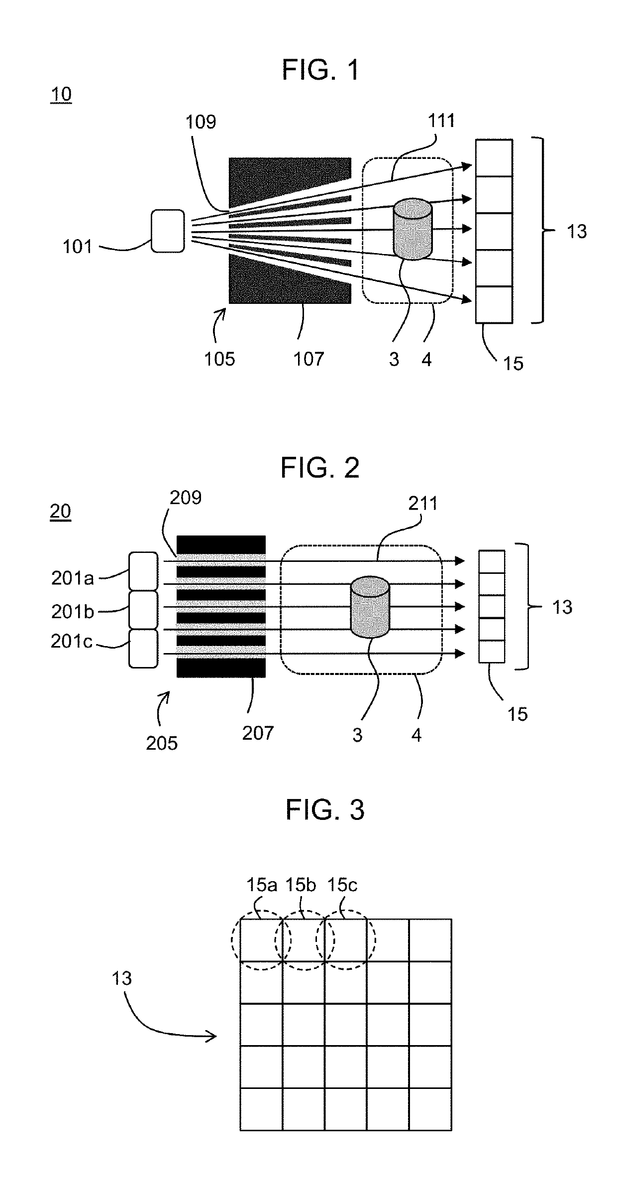
[0001]This application is based upon and claims the benefit of priority from UK Patent Application No. GB 1804679.7, filed on 23 Mar. 2018, the entire contents of which are incorporated by reference.BACKGROUNDTechnical Field[0002]The present disclosure relates to x-ray imaging systems, methods of x-radiography, and methods of manufacture of collimators suitable for use in x-ray imaging systems and methods of x-radiography.Description of the Related Art[0003]Radiography is an imaging technique using x-rays to view or otherwise examine the internal structure of an object such as, for example, a machine component for non-destructive testing purposes, or a patient's body for medical imaging purposes.[0004]Typically, an x-ray generator or source (for example, an x-ray tube) is used to produce a beam of x-rays in a well-known manner, by heating of a cathode filament to produce an electron beam which is accelerated by a potential difference towards a positively charged anode target. Electr...

Claims


Application Information

Patent Timeline
IPC IPC(8): A61B6/03G21K1/02G02B27/30A61B6/00
CPCG21K1/02G02B27/30A61B6/5229A61B6/032G21K1/025A61B6/06A61B6/5205
Inventor CLARK, DANIELBARDEN, TIMOTHY J.
Owner ROLLS ROYCE PLC
Why Eureka
Try Eureka