
Compensating for geometric distortion of images in constrained processing environments

a processing environment and compensation technology, applied in image enhancement, image analysis, instruments, etc., can solve the problems of wasting processing resources, many applications that require real time or low latency performance, and strict time and hardware resource constraints on the amount of time and hardware allocated, so as to achieve effective estimation, reduce processing costs, and reduce processing costs

Active Publication Date: 2019-09-19
DIGIMARC CORP
View PDF0 Cites 7 Cited by
  • Summary
  • Abstract
  • Description
  • Claims
  • Application Information

AI Technical Summary

Benefits of technology

The patent describes a method for efficiently detecting and recovering geometrical transform parameters of embedded data signals in images. The method uses complementary processes to evaluate a large number of geometrical transform candidates based on their ability to map components of the embedded data signal to corresponding components detected in the image. This approach improves the data carrying capacity and robustness of the image, while also enhancing the aesthetic quality of the image by detecting weaker data carrying signals and data signals that are blended into host imagery and other information bearing content on objects. Overall, the method overcomes the problem of wasting computational resources on unfruitful image processing, and provides a more reliable and efficient way to recognize embedded data in images.

Problems solved by technology

A suspect image may not contain expected image structure, and as such, processing expended trying to detect it is a waste of processing resources.
Moreover, many applications require real time or low latency performance, as the image processing task must operate on a real time, incoming stream of image blocks, and there are strict time and hardware resource constraints on the amount of time and hardware allocated to each block.
The image is further distorted, for example, when the object to which it is applied or displayed is distorted.
During use of the object, the image is further distorted (e.g., non-rigid objects are readily deformable during normal use, including when being imaged).
In light of these various sources of geometric distortion and image noise, it is challenging to determine the geometric transform of a suspect image relative to its original state.
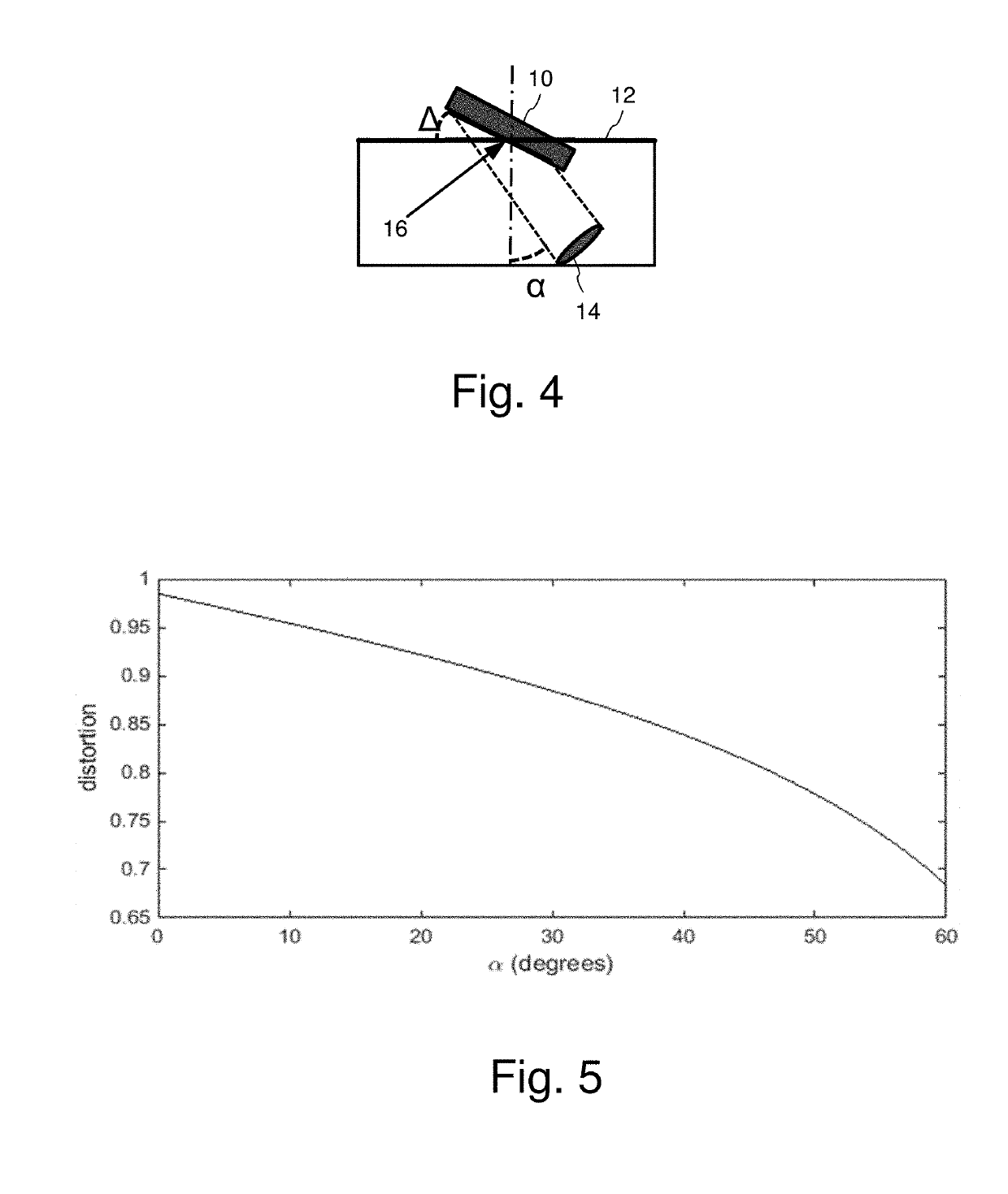
Actual geometric distortion tends to be more complex, with tilt and camera angle in different directions, finite focal length(s) of the camera, etc.
If the camera angle is known, image pre-processing can potentially compensate for it by dividing the image coordinates by cos α. However, this pre-processing may introduce additional noise into the image, even if it is slightly incorrect.
As the camera angle increases, the distortion increases and becomes increasingly difficult to correct accurately.
Further, in practice, additional geometric distortion, such as perspective distortion, is present, which is more challenging to compensate for in applications of image recognition and decoding machine readable data encoded in the distorted image.
While it is possible to approximate a perspective transform with an affine transform, an affine transform is not a perfect approximation.
Recovery of the affine parameters may approximate a perspective distortion, but this approximation is not always sufficient and some amount of correction for the perspective part is sometimes necessary.
However, they can tend to consume significant computational resources or not sufficiently address certain forms of distortion, such as perspective.

Method used


Image

  • Compensating for geometric distortion of images in constrained processing environments
  • Compensating for geometric distortion of images in constrained processing environments
  • Compensating for geometric distortion of images in constrained processing environments

Examples


Embodiment Construction

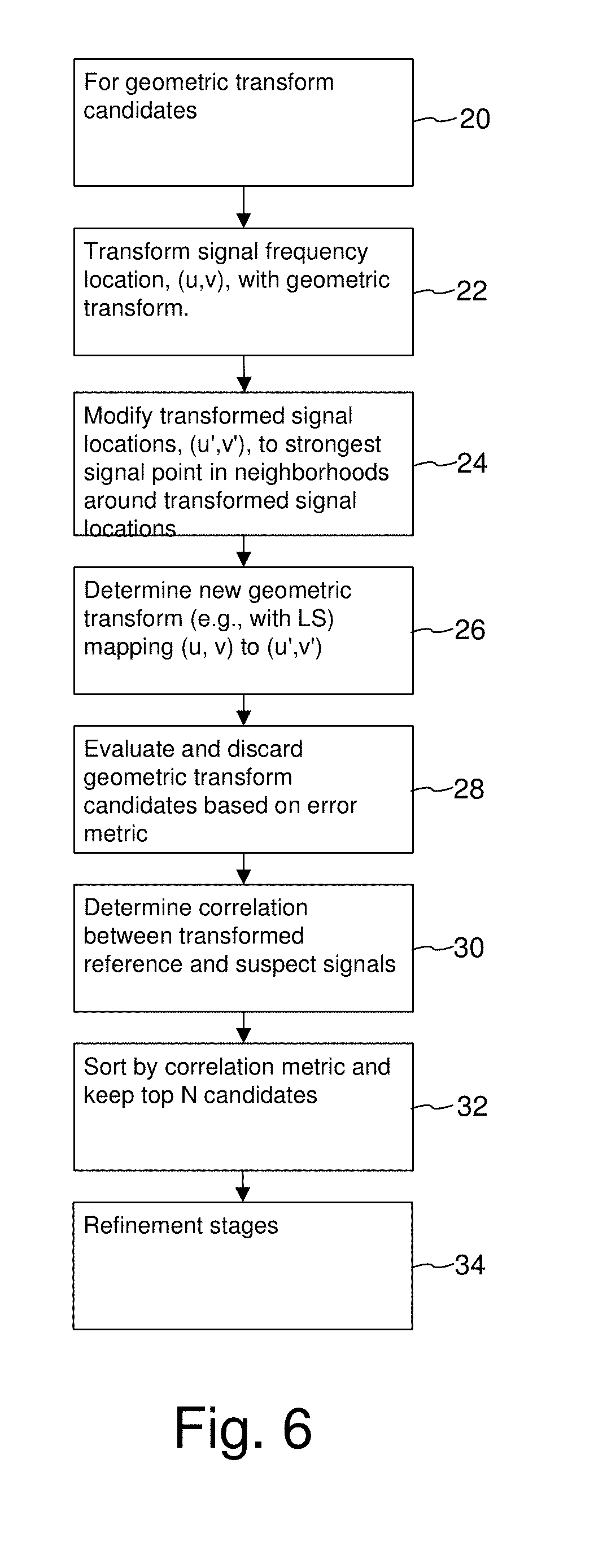
[0047]We begin with a description of our method for determining a geometric transform of an image with reference to FIG. 6. We then describe various alternative implementation details. For additional background, we refer the reader to U.S. Pat. No. 9,182,778 and Provisional Application 62 / 199,710. The International Patent Application counterpart to 62 / 199,710, is WO 2017 / 011801, and both of these applications are hereby incorporated by reference.

[0048]FIG. 6 is a flow diagram illustrating a method for determining a geometric transform of an image. This method is used to find the geometric transform of a reference signal within a suspect image. The method seeks to determine the geometric transform parameters that best approximate the geometric transform between reference signal components and corresponding signal components located in the suspect image. It is not certain that the suspect image contains the reference signal. Moreover, even if it does, it is highly distorted due to geo...


PUM


Abstract

An image processing method determines a geometric transform of a suspect image by efficiently evaluating a large number of geometric transform candidates in environments with limited processing resources. Processing resources are conserved by using complementary methods for determining a geometric transform of an embedded signal. One method excels at higher geometric distortion, and specifically, distortion caused by greater tilt angle of a camera. Another method excels at lower geometric distortion, for weaker signals. Together, the methods provide a more reliable detector of an embedded data signal in image across a larger range of distortion while making efficient use of limited processing resources in mobile devices.

Description

RELATED APPLICATION DATA[0001]This application is a continuation of U.S. application Ser. No. 15 / 628,400, filed Jun. 20, 2017 (now Patent 10,242,434), which is a continuation-in-part of U.S. application Ser. No. 15 / 588,451, filed May 5, 2017, which claims the benefit of U.S. Provisional Application 62 / 332,470, filed May 5, 2016, which is hereby incorporated by reference.TECHNICAL FIELD[0002]The invention relates image signal processing to recover geometric distortion of an image and associated image processing for extracting encoded auxiliary information from images.BACKGROUND AND SUMMARY[0003]For a variety of image processing applications, it is necessary to determine the geometric distortion of an image, and, compensate for it. Technical fields where this is important include image and object recognition. Another application is decoding machine readable data encoded into an optical data carrier within an image. This data carrier may be an overt optical code such as a two-dimension...

Claims


Application Information

Patent Timeline
IPC IPC(8): G06T5/00G06T1/00G06T3/00G06K7/14
CPCG06T2201/0065G06T2201/0601G06T1/0064G06K7/1443G06K7/1447G06T2201/0052G06T2207/20048G06T3/0006G06T3/0012G06T2201/0083G06T1/0021G06T5/006G06T2207/30204G06T3/4084G06T2201/0061G06T5/80G06T3/02G06T3/04
Inventor HOLUB, VOJTECH
Owner DIGIMARC CORP
Learn More