
Dual-pass-through countertop high velocity hot air sterilizer

a sterilizer and countertop technology, applied in the field of dry heat sterilizers, can solve the problems of insufficient microbial kill efficacies across all three dimensions of the sterilization chamber, limited application and capacity of the air handling system of the cox device, and small facilities that have neither space to accommodate nor instrument processing volume, so as to achieve the effect of maintaining thermal uniformity and microbial kill efficacies, and facilitating the use of larger instruments

Active Publication Date: 2019-08-22
INTEGRATED MEDICAL TECH
View PDF3 Cites 3 Cited by
  • Summary
  • Abstract
  • Description
  • Claims
  • Application Information

AI Technical Summary

Benefits of technology

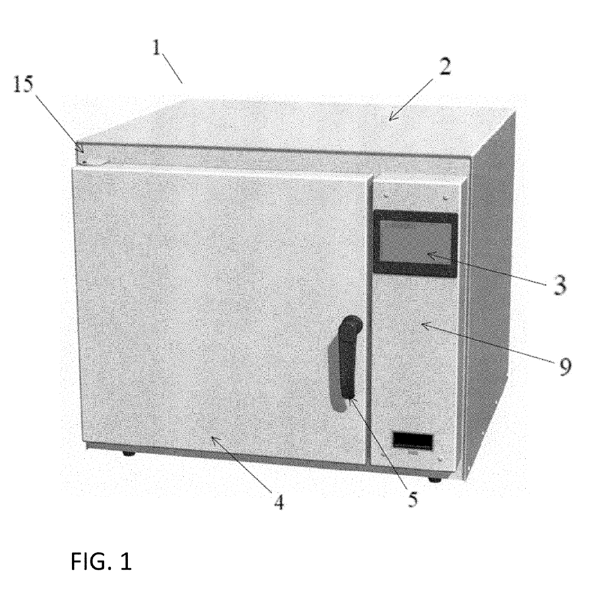
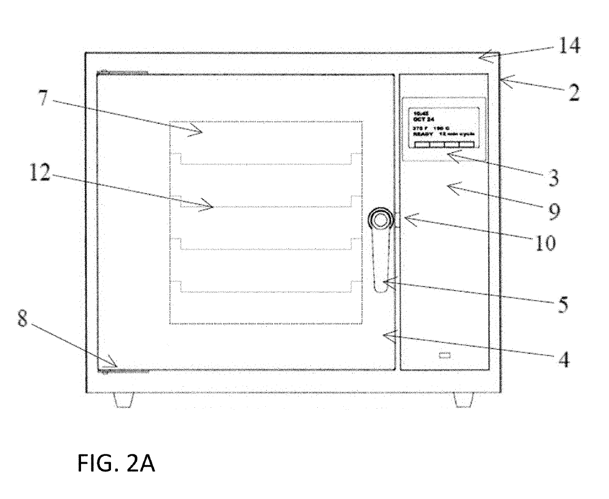
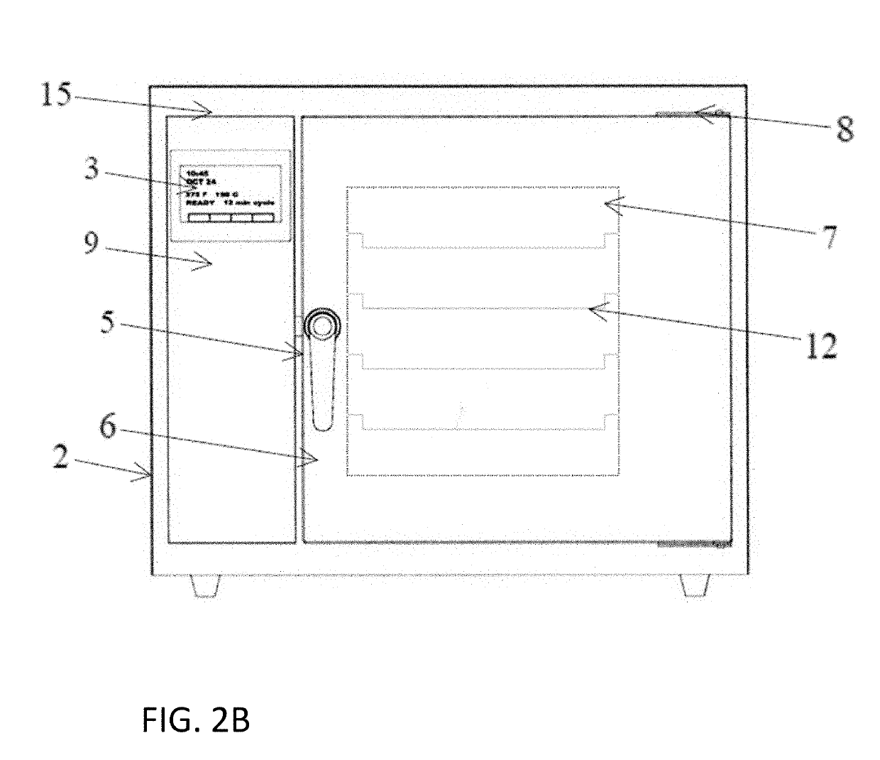
The present invention is a chain counter top hot air sterilizer that improves upon existing sterilization devices by a double door configuration, an air supply heating system, a dual airflow pathway, a temperature sensing monitor, and a closed system to prevent the flow of external air. The sterilizer allows for efficient sterilization of medical, dental, and veterinary instruments in critical-care environments, while maintaining a sterile environment. The air handling system recirculates and reheats air with uniform heat distribution and horizontal airflow velocity to meet the requirements of high velocity hot air sterilization within the sterilization chamber. The closed system seals all sterilizer doors, air handling plenums, vents, and other potential air infiltration areas to maintain a sterile environment during the sterilization cycle. The air handling system includes a fan wheel, electric heater unit, dual hot air supply plenums, air supply wall, sterilization chamber, and air return exhaust for air recirculation. The air handling system is sealed and closed to prevent the infiltration of outside air once a sterilization cycle is initiated.

Problems solved by technology

Attempts to increase the sterilization chamber size under the embodiments of Cox resulted in increasing already large temperature ranges generated in the existing sterilization chamber and resulted in inconsistent and inadequate microbial kill efficacies across all three dimensions of the sterilization chamber.
While effective for instrument sizes and load capacities found in dental and orthodontic practices, the air handling system of the Cox device is limited in application and capability to serve the expanded requirements and needs of a healthcare facility such as a hospital or clinic.
These smaller facilities have neither space to accommodate nor an instrument processing volume to justify use of a large steam sterilizer normally used in hospital Sterile Processing departments.
The Cox sterilizer has inherent design limitations that limit its ability to accommodate a double door configuration and to expand sterilization chamber dimensions required for increased instrument capacity and instrument size.
It has further been demonstrated that expansion of the vertical airflow distance beyond four inches significantly alters airflow velocity, which dramatically reduces air mixing and leads to reduced microbial kill efficacy.
Such limitations would preclude a sterilization chamber with horizontal airflow from having a chamber width greater than four inches.
The design embodied by Cox et al. did not produce an airflow with temperature uniformity prior to reaching the sterilization chamber.
Although the length and design of the air pathway is important in allowing time, distance and airflow interference to homogenize air temperature, this factor alone will not assure temperature uniformity at air entry point to the sterilization chamber.
Increased pathway length, plenum diversions, and ninety-degree turns will assist in air mixing, but large variations in air temperatures generated by heater element exposure cannot be offset by these design components.

Method used


Image

  • Dual-pass-through countertop high velocity hot air sterilizer
  • Dual-pass-through countertop high velocity hot air sterilizer
  • Dual-pass-through countertop high velocity hot air sterilizer

Examples


Embodiment Construction

[0041]The present invention is described in reference to the accompanying drawings and following embodiments that are presented for the purpose of illustration and should not be construed to limit the scope of the invention thereto.

[0042]The present invention relates to medical instrument sterilization. Particularly, a countertop high velocity hot air sterilization apparatus suitable for loading instruments and their containers into the sterilization chamber by means of an entry door and subsequent to the sterilization process removing said instruments and containers by means of a separate exit door into a sterile area of the facility to mitigate environmental contaminant exposure to the sterilized instruments and containers. The sterilization apparatus comprises a countertop housing having an entry door at a front end of a sterilization chamber and an exit door at a back end of the sterilization chamber; the chamber configured to allow non-sterile, contaminated instruments and inst...


PUM

PropertyMeasurementUnit
heightaaaaaaaaaa
depthaaaaaaaaaa
widthaaaaaaaaaa

Abstract

A device and system for sterilizing objects, commonly dental, medical, or veterinary instruments, having a double door configuration that can provide entry of contaminated instruments into a sterilizer from a contaminated area and subsequently, post-sterilization, their pass-through directly into a sterile area through an exit door from said sterilizer. More specifically, the invention is a countertop, high velocity, dry heat sterilization device that is readily adaptable for those clinical areas requiring separation of contaminated and sterile areas for the processing of medical, dental, or veterinary instruments. The sterilization device utilizes a dual airflow pathway and a controlled heat delivery system to deliver to the sterilization chamber the supply air having temperature uniformity and air velocity required of the high velocity dry heat sterilization process.

Description

CROSS-REFERENCE TO RELATED APPLICATIONS[0001]This application claims the benefit of U.S. Provisional Application No. 62 / 632,906, filed Feb. 20, 2018.BACKGROUND OF THE INVENTION[0002]There are three distinct types of dry heat sterilizers: (1) Static hot air sterilizers in which air convection is generated solely by gravity as hot air rises and cooler air descends; (2) Mechanical convection sterilizers in which air is moved by blowers to uniformly distribute heated air and equally transfer heat throughout a load; and (3) High velocity hot air sterilizers in which air is moved at a high rate, as much as 2500 feet per minute, with flowing air serving as a heat transfer medium. Both static air and mechanical convection sterilizers require minimally one hour (at 340° F.) or two hours (at 320° F.) to achieve sterilization whereas high velocity hot air sterilizer can sterilize in six to twelve minutes (at 375° F.), depending on instrument type or packaging.[0003]A high velocity hot air ster...

Claims


Application Information

Patent Timeline
Patent Type & Authority Applications(United States)
IPC IPC(8): A61L2/06
CPCA61L2/06A61L2202/15A61L2202/14A61L2202/24Y02A50/20
Inventor SMITH, WILLIAM BRYANLINSE, MICHAEL HOWARDSLAVIK, NELSON SIGMAN
Owner INTEGRATED MEDICAL TECH
Learn More