
Back pressure valve having a reduced pressure drop required for fluid to pass through the valve

a back pressure valve and valve body technology, applied in the direction of valve arrangements, safety valves, check valves, etc., can solve the problems of high price of screw elements and damage, and achieve the effect of reducing internal pressure drop

Inactive Publication Date: 2019-08-15
CHAPMAN JR WALTER R
View PDF0 Cites 0 Cited by
  • Summary
  • Abstract
  • Description
  • Claims
  • Application Information

AI Technical Summary

Benefits of technology

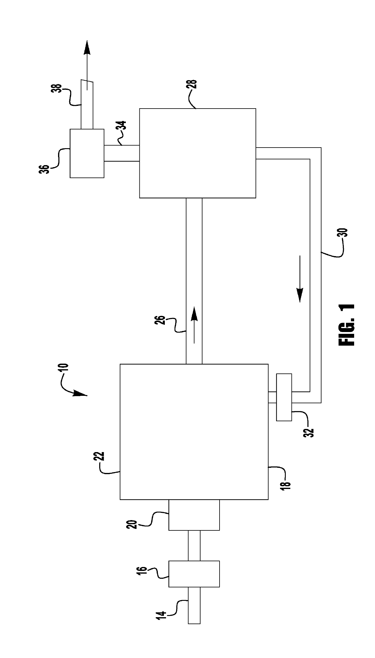
The present invention is a back-pressure valve used with a compressor. The valve has a unique design that reduces the pressure drop required for the fluid to pass through. The valve includes a self-modulating back pressure valve with an independent check valve that opens at a given pressure. The valve has a back body wall with an orifice that forms a ratio of area to diameter of the orifice. The ratio of length of a radius line to the diameter of the orifice is also important. By using a specific design, the valve can minimize the pressure drop required for the fluid to pass through.

Problems solved by technology

Preventing the input of dirt and dust protects the screw elements which are very expensive and can be damaged.

Method used


Image

  • Back pressure valve having a reduced pressure drop required for fluid to pass through the valve
  • Back pressure valve having a reduced pressure drop required for fluid to pass through the valve
  • Back pressure valve having a reduced pressure drop required for fluid to pass through the valve

Examples


Embodiment Construction

[0027]In the description that follows, numerous details are set forth in order to provide a thorough understanding of the present invention. It will be appreciated by those skilled in the art that variations of these specific details are possible while still achieving the results of the present invention. Well-known processing steps are generally not described in detail in order to avoid unnecessarily obfuscating the description of the present invention.

[0028]In the description that follows, exemplary dimensions may be presented for an illustrative embodiment of the invention. The dimensions should not be interpreted as limiting. They are included to provide a sense of proportion. Generally speaking, it is the relationship between various elements, where they are located, their contrasting compositions, and sometimes their relative sizes that is of significance.

[0029]In the drawings accompanying the description that follows, often both reference numerals and legends (labels, text de...


PUM


Abstract

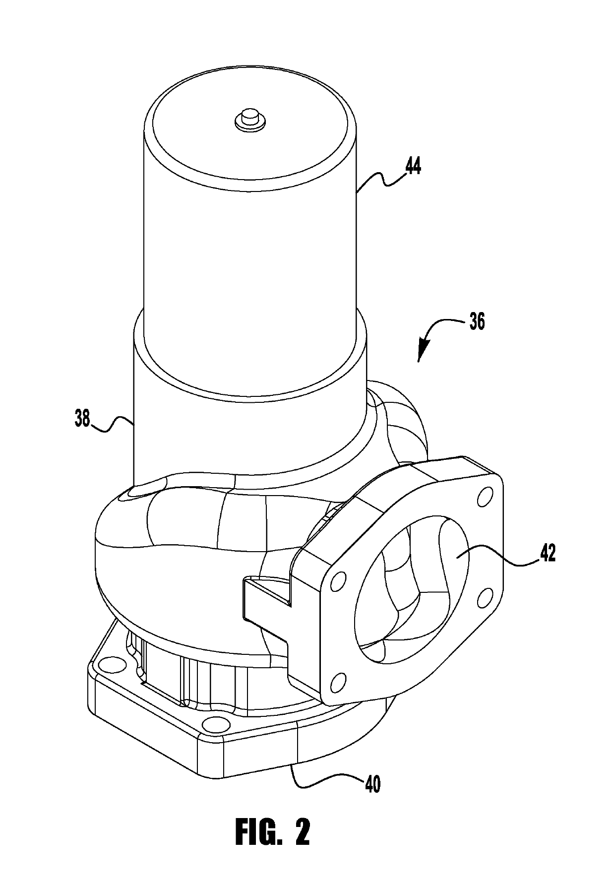
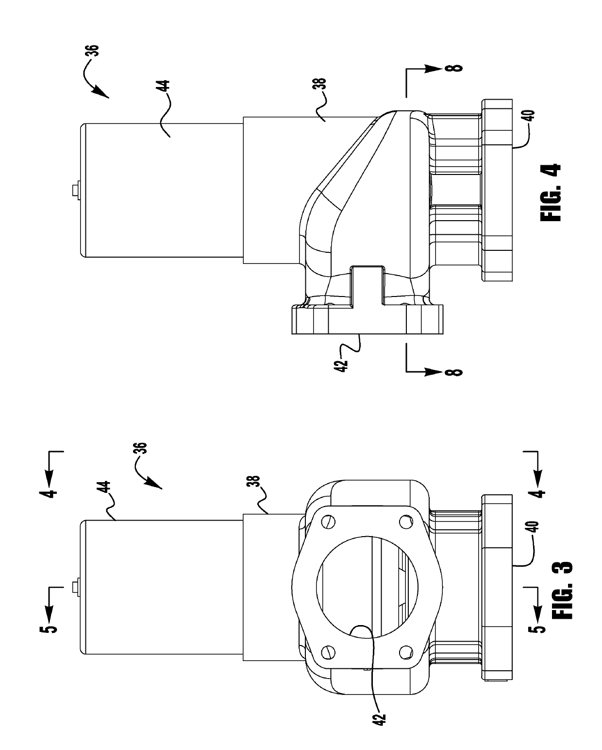
A back-pressure valve having a lower internal pressure drop used in conjunction with a compressor. The back-pressure valve includes a valve body with a fluid inlet and a fluid outlet wherein the fluid inlet is disposed at an angle of 90 degrees to the fluid outlet. The valve body includes a self-modulating back pressure valve set to open at a given pressure. The self-modulating back pressure valve includes a valve for moving towards and away from a valve seat to allow fluid flow from the fluid inlet to the fluid outlet when the valve is spaced from the valve seat. The valve seat forms an orifice. The ratio of the area of the orifice to an area of the fluid flow channel from the valve inlet to the valve outlet of the minimum pressure valve reduces the pressure drop required for the fluid to pass thru the valve.

Description

FIELD OF INVENTION[0001]The present invention relates generally to rotary screw type compressor systems, and, more specifically, the present invention relates to a high efficiency, minimum pressure valve with an integrated independent check valve featuring a lower internal pressure drop.BACKGROUND OF INVENTION[0002]Compressors are used in a wide variety of industrial and residential applications. Compressors are also used to inflate or otherwise impart a fluid force on an external object such as tires or pneumatic tools. It is always desirable that a compressor provide consistent and efficient operation to ensure that the particular application (e.g., pneumatic tools) functions properly. To that end, modulation of compressor inlet and outlet conditions can provide reliable and efficient compressor and system operation.[0003]A typical rotary-screw gas compressor operates as follows. Note that all references to gas refers to all gasses i.e. methane, nitrogen, argon, helium, air, etc. ...

Claims


Application Information

Patent Timeline
Patent Type & Authority Applications(United States)
IPC IPC(8): F16K17/10
CPCF16K17/105F16K15/028
Inventor CHAPMAN, JR., WALTER R.
Owner CHAPMAN JR WALTER R
Learn More