Accumulator grid
A battery and grid technology, applied in the direction of electrode carrier/collector, etc., can solve the problems of outflow, uneven potential distribution, large internal voltage drop of the battery, etc., and achieve the effect of prolonging the service life and shortening the conduction path of the current
Inactive Publication Date: 2010-09-01
JIANGSU OLITER ENERGY TECH
View PDF0 Cites 1 Cited by
- Summary
- Abstract
- Description
- Claims
- Application Information
AI Technical Summary
Problems solved by technology
[0002] Currently used as a battery grid, the grid with vertical vertical ribs is generally used. The battery plate made of this structure grid has a long current conduction path, which causes a large internal pressure drop of the battery, resulting in The reduction of output power; when used as a starting battery, the large discharge capacity at the moment of high-power output will cause de-current, so that the current and potential distribution on the grid will be uneven, and the lead paste on the plate will change unevenly and fall off. , not only reduces the holding capacity of the lead paste, but also causes the connection between the positive and negative electrodes, resulting in an increase in self-discharge, which reduces the capacity and the service life of the battery
Method used
View moreImage
Smart ImageViewing Examples
Examples
Embodiment Construction
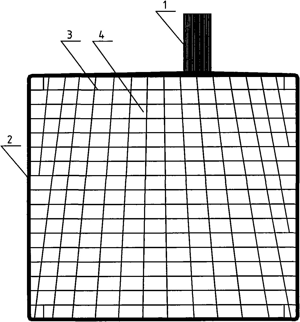
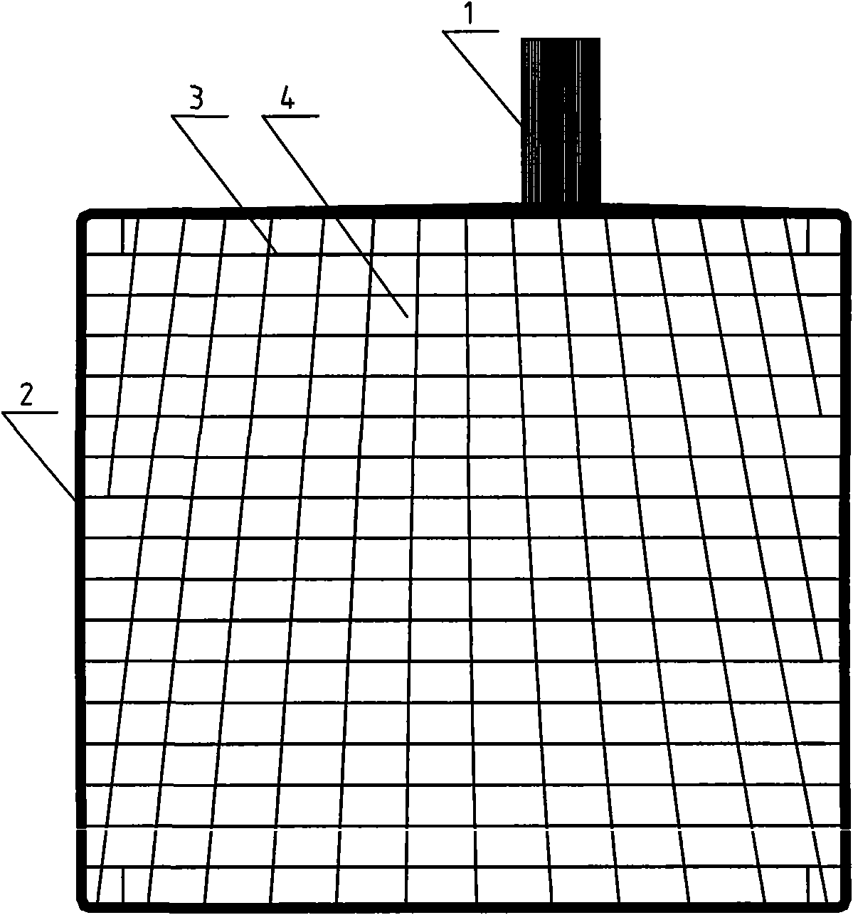
[0008] The present invention includes a tab 1, a frame 2, a transverse rib 3 and a longitudinal rib 4, and the longitudinal rib 4 is radially distributed along the middle of the frame to both sides on the side of the tab.
[0009] In the present invention, in order to have more space for accommodating active materials and increasing the capacitance, the transverse ribs 3 can be designed to face opposite half ribs.
Login to View More PUM
 Abstract
The invention relates to an accumulator grid, which comprises a lug, a frame, transverse bars and longitudinal bars, wherein the longitudinal bars are distributed along the middle part of the frame from the lug side towards the two sides in a way of radioactive rays. In the accumulator grid provided by the invention, based on the principle that the length of the bevel edge is less than that of the sum of two right-angle sides, the longitudinal bars on encryption board grid which are not vertical to the bottom side are intensified to shorten the conduction path of an electric current. The accumulator grid provided by the invention effectively shortens the conduction path of the electric current, which means the defect of long current conduction path in the prior art is overcome. Thus, the accumulator grid effectively reduces the internal drop of an accumulator and prolongs the service life of the accumulator.
Description
technical field [0001] The invention relates to battery grids and belongs to the technical field of electric power storage. Background technique [0002] Currently used as a battery grid, the grid with vertical vertical ribs is generally used. The battery plate made of this structure grid has a long current conduction path, which causes a large internal pressure drop of the battery, resulting in The reduction of output power; when used as a starting battery, the large discharge capacity at the moment of high-power output will cause de-current, so that the current and potential distribution on the grid will be uneven, and the lead paste on the plate will change unevenly and fall off. , not only reduces the holding capacity of the lead paste, but also causes the connection between the positive and negative electrodes, resulting in an increase in self-discharge, which reduces the capacity and the service life of the battery. Contents of the invention [0003] The purpose of ...
Claims
Login to View More Application Information
Patent Timeline
 Patent Type & Authority Applications(China)
IPC IPC(8): H01M4/73H01M4/72
CPCY02E60/10
Inventor 袁朝勇袁朝明
Owner JIANGSU OLITER ENERGY TECH
- R&D Engineer
- R&D Manager
- IP Professional
- Industry Leading Data Capabilities
- Powerful AI technology
- Patent DNA Extraction
Learn More Browse by: Latest US Patents, China's latest patents, Technical Efficacy Thesaurus, Application Domain, Technology Topic, Popular Technical Reports.
© 2024 PatSnap. All rights reserved.Legal|Privacy policy|Modern Slavery Act Transparency Statement|Sitemap|About US| Contact US: help@patsnap.com


