
Isothermal chemical reactor with plate heat exchanger

a technology of isothermal chemical reactor and plate heat exchanger, which is applied in indirect heat exchangers, laminated elements, lighting and heating apparatus, etc., can solve the problems of unable to discharge or refill catalysts, drawbacks of a more complex and expensive construction, and the solution is not always fully satisfying

Active Publication Date: 2015-09-01
CASALE SA
View PDF13 Cites 1 Cited by
  • Summary
  • Abstract
  • Description
  • Claims
  • Application Information

AI Technical Summary

Benefits of technology

[0027]The invention is particularly advantageous when the heat exchanger is equipped with the sandwiched plates as defined above. Said plates have a strong resistance to a high pressure difference between inside and outside (such as 100 bars and beyond), and have been found to reduce internal pressure drop, so their use can be preferable in comparison, for example, to inflated pillow plates. Due to their structure with the internal channels defined by the spacer elements, however, such plates does not allow to implement a solution as seen in FIG. 7, as it would not be possible to easily connect the internal channel(s), near the axis of the reactor, to the respective fluid duct. With the known art, a heat exchanger with sandwiched plates would require the expensive and complex arrangement of FIG. 6 to avoid interference of the internal ends of the fluid ducts, thus limiting the possible applications of these exchangers.
[0028]The invention however can be used with any kind of heat-exchange plates, including the aforementioned inflated plates, maintaining the advantage of a correct spacing between the internal, converging ends of the fluid ducts, together with low cost and ease of installation.

Problems solved by technology

Hence, the converging ends of said radial pipes can interfere each other or, in any case, the interspace between converging ends may become too little, causing some practical disadvantages, such as obstacle to discharge or refill the catalyst.
This solution however has the drawbacks of a more complex and expensive construction.
This solution however is not always fully satisfying: the plates are more difficult to realize and the fluid flow inside is disturbed by cuts 113; moreover a transversal flow must be allowed inside the plates, in order to equalize the outlet flow and compensate for presence of said cuts 113.
The solutions of FIGS. 6 and 7 are sometimes used in combination, leading however to even more complex and expensive heat exchangers.
The above problem is felt especially in reactors for strongly exothermal reactions, where the heat exchange fluid is a liquid evolving at least partially to a vapour and the collectors need a larger cross section.
This is the case for example of reactors wherein the heat removed from the chemical reaction is used to produce steam, and interference between converging ends of the large steam collectors is difficult to avoid.

Method used


Image

  • Isothermal chemical reactor with plate heat exchanger
  • Isothermal chemical reactor with plate heat exchanger
  • Isothermal chemical reactor with plate heat exchanger

Examples


Embodiment Construction

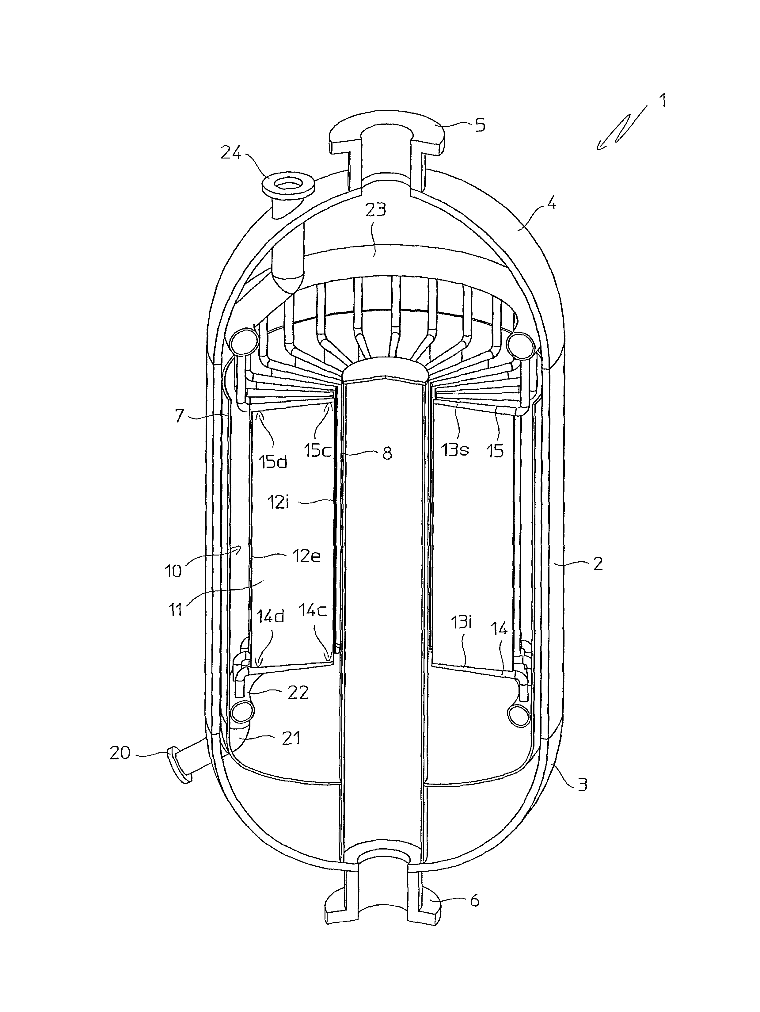
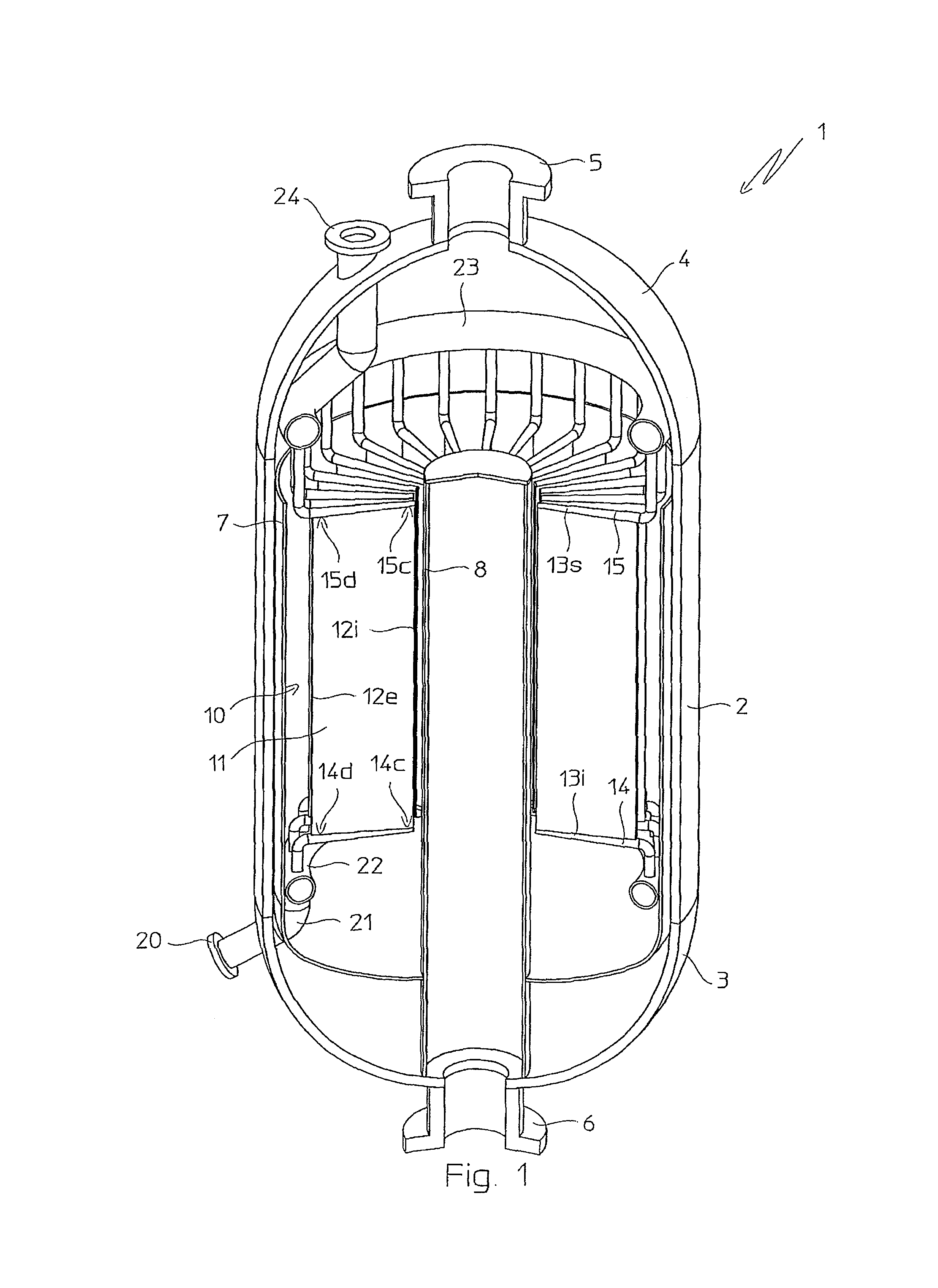
[0035]With reference to FIG. 1, a radial-flow isothermal chemical reactor 1 is shown which essentially comprises a vertical-axis cylindrical shell 2, a lower end 3 and an upper end 4, respectively with an inlet flange 5 for the fresh charge of reagents, and an outlet flange 6 for the products of a chemical reaction.

[0036]The reactor 1 contains an annular catalytic rack, which is per se known and not described in detail, containing an appropriate catalyst and externally delimited by a cylindrical perforated wall 7. The reagents flow in a radial direction, from an interspace between the wall 7 and the shell 2, to a central collector 8 which is in communication with the outlet flange 6. The annular space defined by the catalytic rack is substantially the reaction space, where the reagents are converted into products.

[0037]An axial-flow plate heat exchanger 10 is mounted inside the reactor 1, immersed in the catalyst. The heat exchanger 10 has substantially an annular structure, with ra...


PUM


Abstract

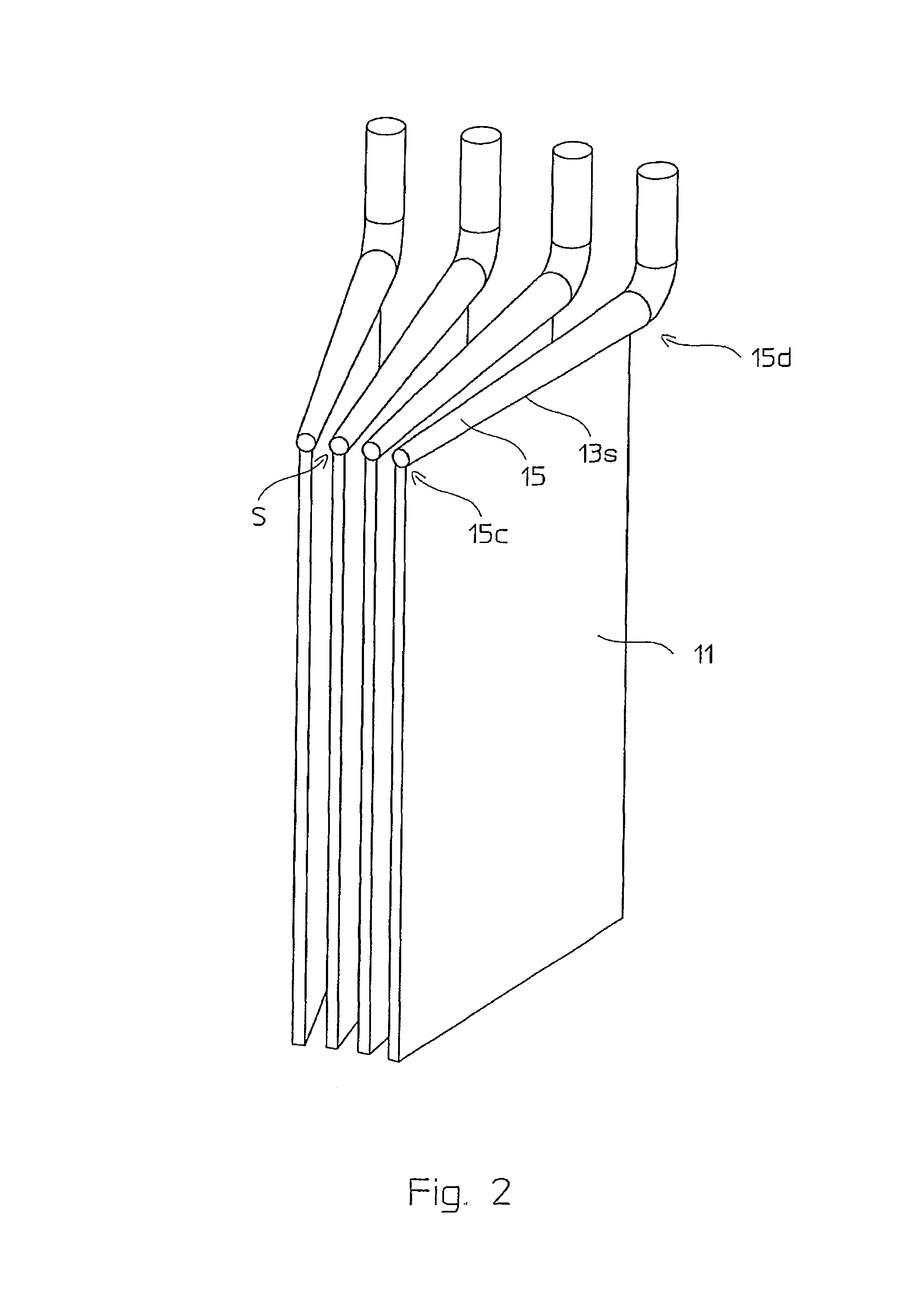
A chemical isothermal reactor (1) with internal plate heat exchanger (10) having heat-exchange radial plates (11), and radial ducts (14, 15) parallel to sides (13i, 13s) of the plates (11) for distributing and collecting a heat exchange fluid, said radial ducts having a portion with a smaller cross section near the inner converging ends (14c, 15c).

Description

FIELD OF THE INVENTION[0001]The invention relates to the field of isothermal chemical reactors equipped with an internal plate heat exchanger.[0002]The invention is applicable, for example, to isothermal or pseudo-isothermal chemical reactors for exothermic or endothermic heterogeneous reactions, wherein the internal heat exchanger is immersed in a catalytic layer, or to reactors where the internal heat exchanger, in operation, is immersed in a fluid.PRIOR ART[0003]Isothermal or pseudo-isothermal chemical reactors are reactors equipped with an internal heat exchanger adapted to maintain the temperature of the reaction in a range of optimal efficiency, by providing or removing heat from the reagents. Isothermal reactors are widely used, for example, in methanol synthesis plants, where the reactor comprises an internal cooling heat exchanger to remove heat generated by the exothermic methanol synthesis reaction.[0004]Isothermal reactors equipped with a plate heat exchanger are known t...

Claims


Application Information

Patent Timeline
Patent Type & Authority Patents(United States)
IPC IPC(8): B01J19/00F28F9/007F28F9/00F28F3/14F28F3/12F28F3/00F28D9/00F28D1/00F28F9/02B01J19/24F28F9/013B01J8/02B01J8/00
CPCB01J8/0285B01J8/0214F28D9/0006F28D9/0062F28F9/0263B01J2208/0015
Inventor RIZZI, ENRICOFILIPPI, ERMANNOTAROZZO, MIRCO
Owner CASALE SA
Learn More