
Systems and methods for variable pressure electrochemical carbon dioxide reduction

Active Publication Date: 2019-08-01
AIR CO HLDG INC
View PDF0 Cites 5 Cited by
  • Summary
  • Abstract
  • Description
  • Claims
  • Application Information

AI Technical Summary

Benefits of technology

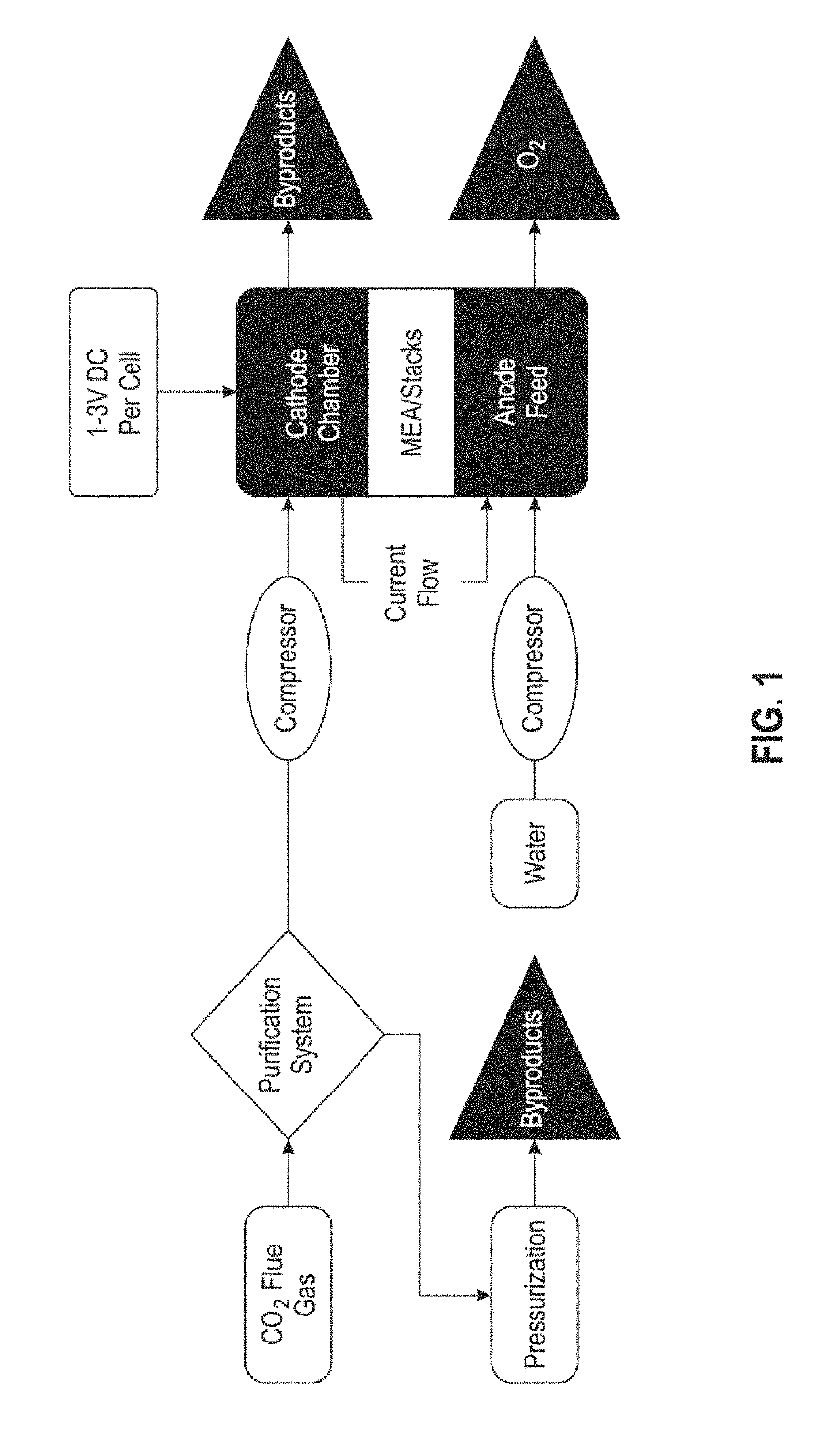
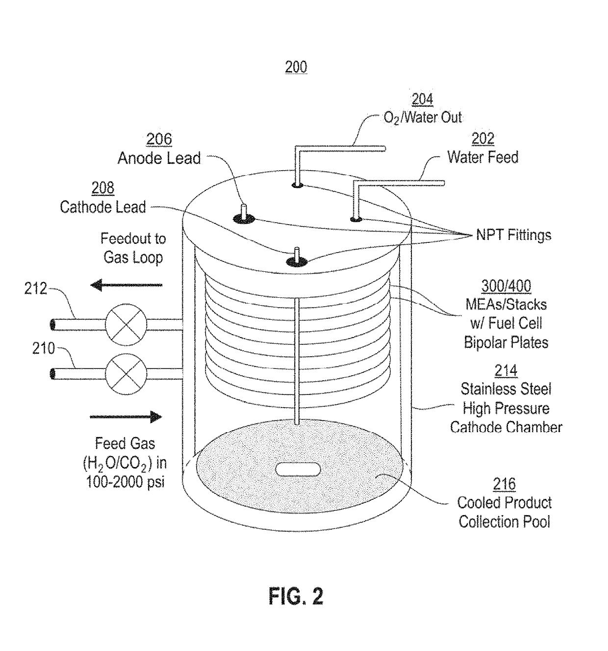
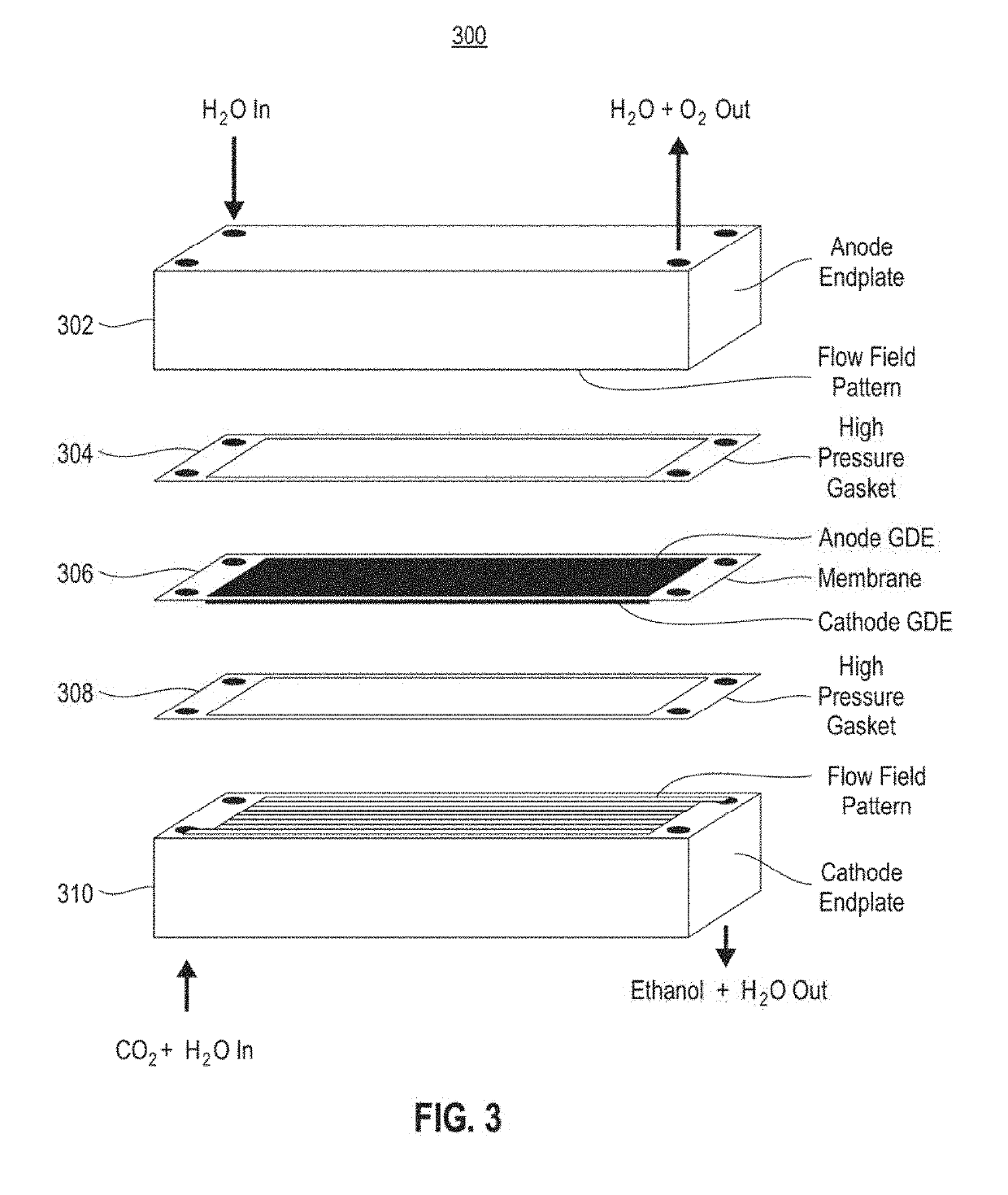
The present patent describes an electrode assembly and an electrochemical reactor for reducing carbon dioxide to produce ethanol. The electrodes are placed between a polymer electrolyte membrane and a cathode catalyst. The cathode endplate allows the polymer membrane to be in fluid communication with the surrounding atmosphere. The method involves supplying a catholyte and an anolyte to the membrane sides and applying a voltage to reduce CO2 to ethanol. The produced ethanol can be used to make alcoholic beverages. The technical effects include efficient and efficient production of alcoholic beverages from carbon dioxide reduction.

Problems solved by technology

However, methods of efficiently transforming carbon dioxide into useful chemicals are still needed.

Method used


Image

  • Systems and methods for variable pressure electrochemical carbon dioxide reduction
  • Systems and methods for variable pressure electrochemical carbon dioxide reduction
  • Systems and methods for variable pressure electrochemical carbon dioxide reduction

Examples


example 1

ty of Various Catalysts

[0076]A Nafion-based MEA was prepared with various metal oxide or molecular cathode layer catalysts layered on top of it. For each catalyst tested, an MEA stack was placed into a pressure vessel and sandwiched between either a graphite or copper cathode flow plate and a platinum-coated titanium anode flow plate. CO2 was introduced into the reactor at pressures between 1000 and 1500 psi, and voltages were applied across the cell from a DC power source. The results of the reactions are listed in Table 1, where bpy=2,2′-bipyridine, and sb=surface bound to an antimony-doped tin oxide conductive support.

TABLE 1Reaction Conditions for Various CatalystsPrimaryVoltageCurrentproductCatalystLifetime(2-cell)Density(% yield)Re(bpy)(CO)3(sb)2.0  91 mA / cm2NotDetectableCopper Oxide7+ days2.1 786 mA / cm2Ethanol (7%)CuMn Mixed Oxide7+ days2.51.01 A / cm2FormicAcid (71%)CuFe Mixed Oxide34 hours2.1 402 mA / cm2Methanol(3%)

example 2

n of Ethanol Using Various Catalysts

[0077]Various Copper-based catalysts were tested for their capacity to catalyze the reduction of CO2 to ethanol in a Nafion-based or Selemion-based MEA. For each tested catalyst, an MEA stack was placed into a pressure vessel sandwiched between a copper cathode flow plate and a platinum-coated titanium anode flow plate. CO2 was introduced into the reactor at a pressure of approximately 1000 psi, and voltages were applied across the cell from a DC power source. The results are presented in Table 2, where the first two entries used a Nafion-based membrane and the last used a Selemion-based membrane.

PrimaryVoltageCurrentproductCatalystLifetime(2-cell)Density(% yield)Copper oxide7+ days2.1786 mA / cm2Ethanol (7%)Copper oxide on tin 5 days2.1572 mA / cm2Ethanol (3%)oxide supportCopper oxide7+ days2.0415 mA / cm2Ethanol (45%)nanoparticles


PUM


Abstract

Electrochemical devices, such as membrane electrode assemblies and electrochemical reactors, are described herein, as well as and methods for the conversion of reactants such as carbon dioxide to value-added products such as ethanol. In certain aspects, the membrane electrode assemblies are configured to allow for distributed pressure along the cathodic side of a membrane electrode assembly is described. The pressure vessel acts as a cathode chamber, both for the feed of reactant carbon dioxide as well as collection of products. The designs described herein improves the safety of high pressure electrochemical carbon dioxide reduction and allows for varied pressures to be used, in order to optimize reaction conditions. Configurations optimized for producing preferred products, such as ethanol, are also described.

Description

REFERENCE TO RELATED APPLICATIONS[0001]This application is a continuation of International Patent Application No. PCT / US2017 / 056589, filed Oct. 13, 2017, which claims the benefit of U.S. Provisional Patent Application No. 62 / 408,172, filed Oct. 14, 2016, U.S. Provisional Patent Application No. 62 / 433,828, filed Dec. 14, 2016, and U.S. Provisional Patent Application No. 62 / 468,676, filed Mar. 8, 2017, the contents of each of which are fully incorporated by reference herein in their entireties.BACKGROUND OF THE INVENTION[0002]Plants use photosynthesis to convert carbon dioxide, water, and solar energy into chemical energy by creating sugars and other complex hydrocarbons. This effectively stores the energy in absorbed photons from the sun in the chemical bonds of a carbon-based compound. This process has been supporting the Earth's ecosystem and balancing carbon dioxide concentration in our atmosphere for billions of years, and humans use this process to grow crops for food and chemic...

Claims


Application Information

Patent Timeline
IPC IPC(8): C25B3/04C12G3/04C25B9/20C25B15/08C25B9/19C25B3/25
CPCC25B3/04C12G3/04C25B9/206C25B15/08C12G3/00C25B9/00C25B3/25C25B9/77Y02E60/50C25B9/05C25B9/19C25B9/70
Inventor SHEEHAN, STAFFORD WHEELER
Owner AIR CO HLDG INC
Learn More