
Apparatus and method for using solar radiation in electrolysis process

a technology of solar radiation and electrolysis process, which is applied in the field of solar systems, can solve the problems of increasing the cost of cosub>2 /sub>storage, affecting the wellbeing of the planet, and presently not suitable for base-load electricity supply,

Inactive Publication Date: 2015-02-19
YEDA RES & DEV CO LTD
View PDF14 Cites 5 Cited by
  • Summary
  • Abstract
  • Description
  • Claims
  • Application Information

AI Technical Summary

Benefits of technology

The present invention is a new way to produce clean energy using solar energy to create products that are cost-effective and environmentally friendly. The method also helps reduce CO2 emissions and the need for sequestration of CO2. It also offers a cost-effective alternative for liquid fuel for transportation. Overall, this invention provides a solution for efficient and high-rate production of clean and low-cost products.

Problems solved by technology

However, since these resources are intermittent and there are no cost effective large scale means for storing electricity, solar and wind power are presently not suitable for base-load electricity supply and can only be used in combination with other resources to supply a relatively small portion (5%-20%) of the total power supply.
At the same time, global CO2 emission poses a significant threat to the wellbeing of the planet.
CO2 capture and sequestration is being developed as a possible solution, but the proposed solutions for long term CO2 storage are rather problematic and expensive.
During electrolysis, carbon may deposit on the electrodes, which decreases their efficiency, and eventually stops the process.

Method used


Image

  • Apparatus and method for using solar radiation in electrolysis process
  • Apparatus and method for using solar radiation in electrolysis process
  • Apparatus and method for using solar radiation in electrolysis process

Examples


Embodiment Construction

[0057]The present invention will be understood and appreciated more fully from the following detailed examples taken in conjunction with the drawings.

[0058]In this disclosure, the term “comprising” is intended to have an open-ended meaning so that when a first element is stated as comprising a second element, the first element may also include one or more other elements that are not necessarily identified or described herein, or recited in the claims.

[0059]In the following description, for the purposes of explanation, numerous specific details are set forth in order to provide a thorough understanding of the to present invention. It should be apparent, however, that the present invention may be practiced without these specific details, or while using other details.

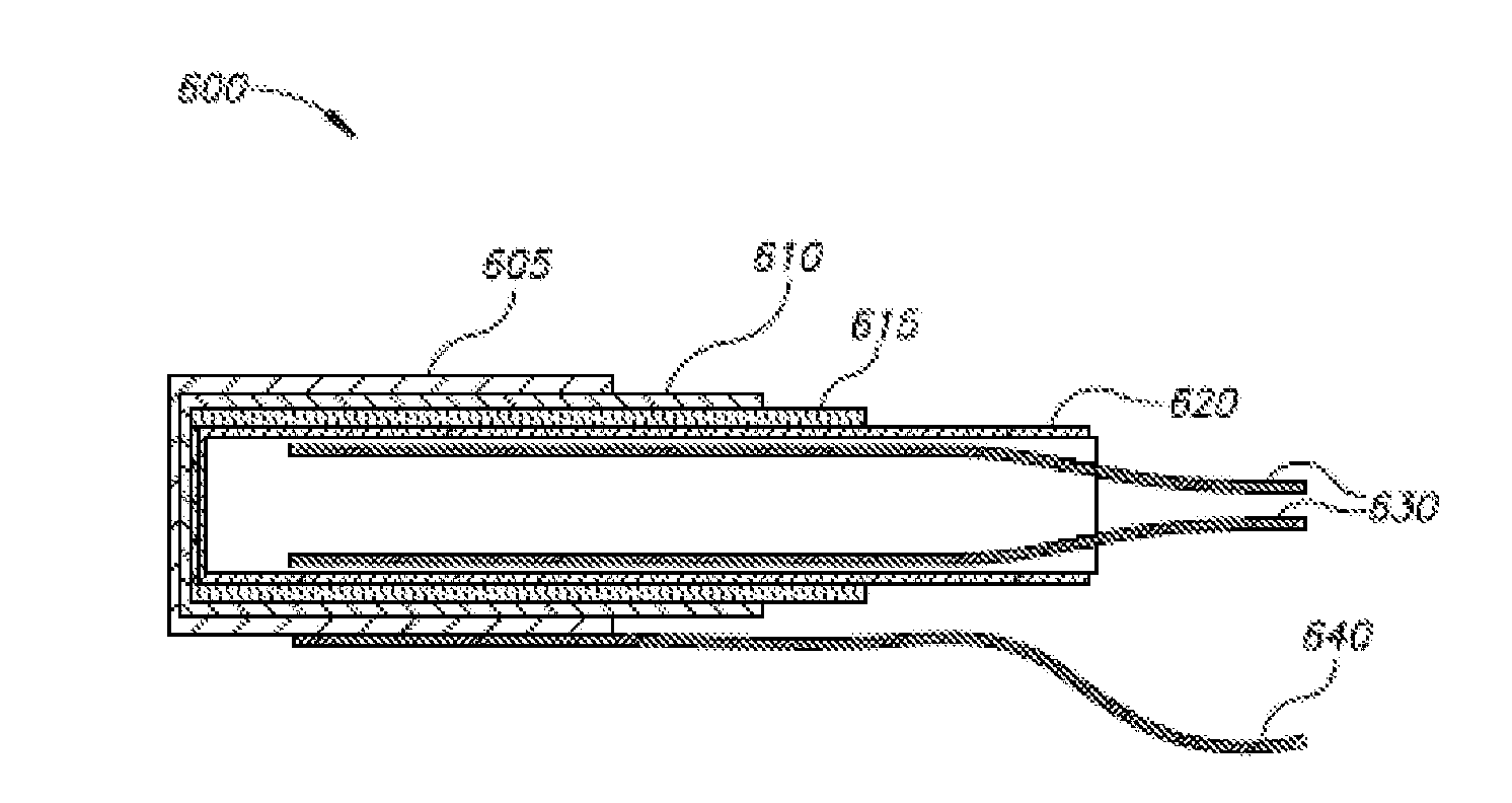
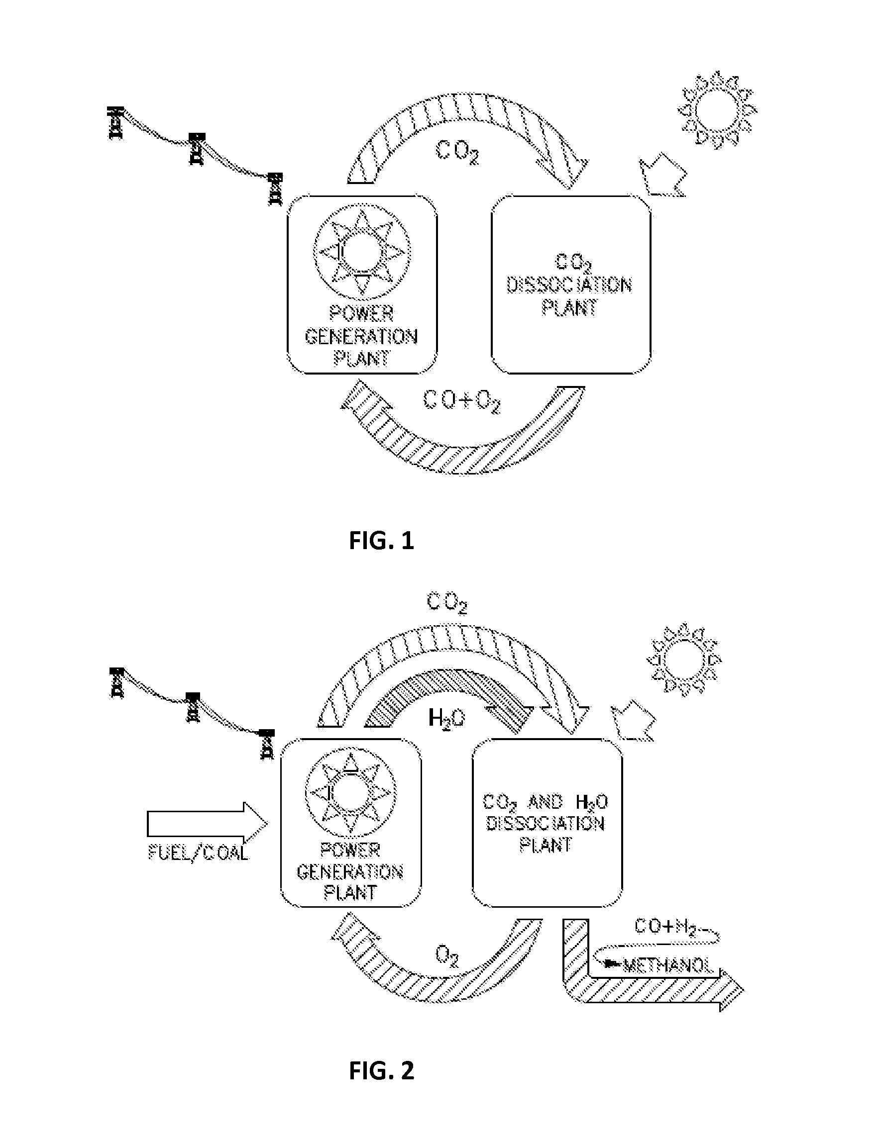
[0060]FIG. 1 illustrates a schematic representation of solar-driven dissociation of recycled CO2 emitted from a power plant, to CO and O2. Oxy-fuel combustion of the CO with oxygen produced in the process eliminates the ne...


PUM

PropertyMeasurementUnit
Flow rateaaaaaaaaaa
Structureaaaaaaaaaa
Transparencyaaaaaaaaaa

Abstract

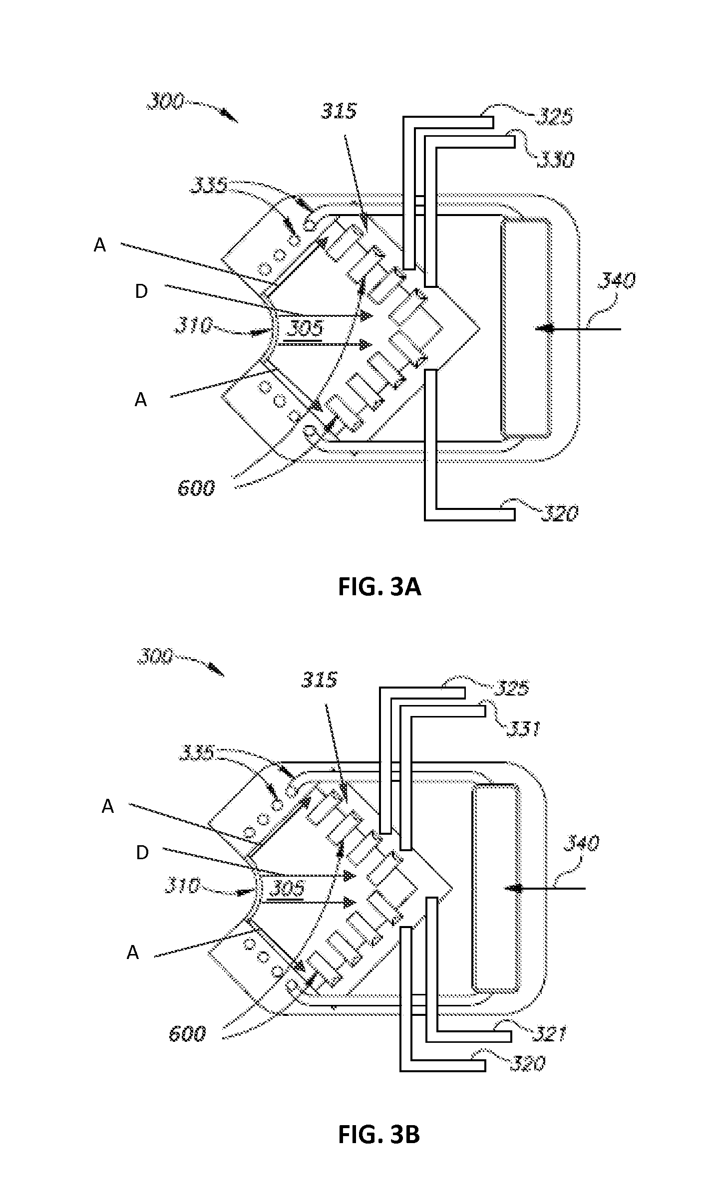
A solar-driven apparatus is provided having: a cavity having at least one optical window for collecting electromagnetic radiation associated with solar energy impinging on said at least one optical window; a reaction assembly located inside the cavity and adapted to enable carrying out electrolysis process of at least one raw fluid utilizing energy derived partially from the solar radiation and partially from an electric source; one or more ingress units operative to allow introduction of the raw fluid into the apparatus; and one or more egress units operative to allow exit of the electrolysis process' products from the solar driven apparatus.

Description

FIELD OF THE INVENTION[0001]The present invention relates in general to solar systems used for carrying out chemical reactions, and particularly to solar systems and methods utilizing CO2 and / or H2O as their raw materials.BACKGROUND OF THE INVENTION[0002]The technologies developed for utilization of abundant intermittent renewable energy resources such as solar and wind energy have reached, or are approaching, acceptable efficiency, reliability and cost levels. However, since these resources are intermittent and there are no cost effective large scale means for storing electricity, solar and wind power are presently not suitable for base-load electricity supply and can only be used in combination with other resources to supply a relatively small portion (5%-20%) of the total power supply. Therefore, the success or failure in commercializing the widespread use of renewable energy resources strongly depends on effective storage means for storing energy derived from renewable resources...

Claims


Application Information

Patent Timeline
IPC IPC(8): C25B1/00C25B9/08C25B1/10C25B9/18C25B9/19
CPCC25B1/003C25B9/18C25B1/00C25B1/10C25B9/08C25B15/00C25B1/04C25B9/00F24S20/20Y02E60/36Y02P20/133C25B1/55C25B9/73C25B9/70C25B9/19
Inventor KARNI, JACOBALIOSHIN, YURYBANITT, DAVIDSCHEINER, DAVIDHARPAZ, ROIFINAROV, BARUCH
Owner YEDA RES & DEV CO LTD
Learn More