
Vessel access catheter

a catheter and valve technology, applied in balloon catheters, medical science, surgery, etc., can solve the problems of long-term disability, difficult operation of distal thrombosis, and operator learning curve, and achieve the effect of preventing the kickback of the endovascular devi

Inactive Publication Date: 2019-06-27
WALZMAN DANIEL EZRA
View PDF3 Cites 2 Cited by
  • Summary
  • Abstract
  • Description
  • Claims
  • Application Information

AI Technical Summary

Benefits of technology

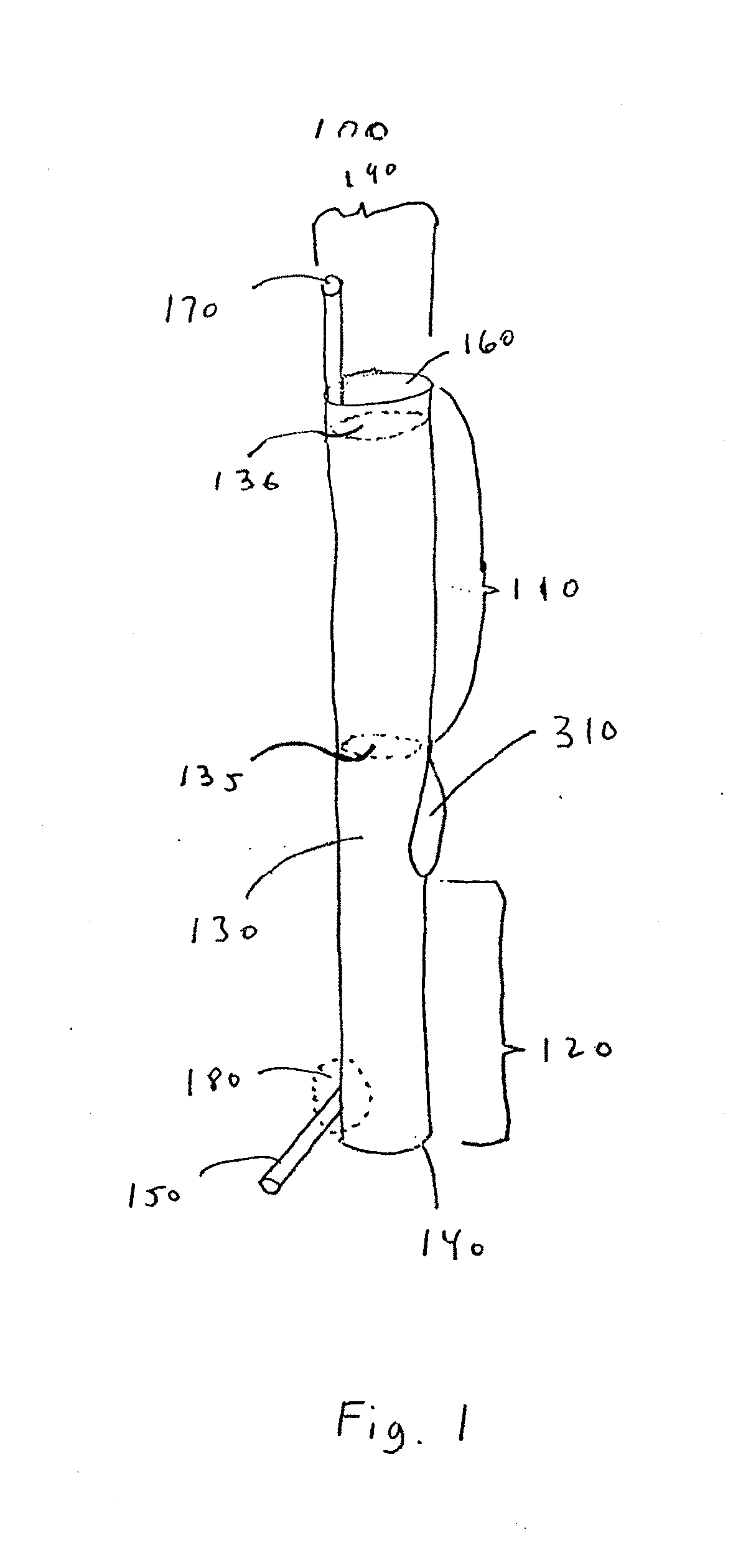
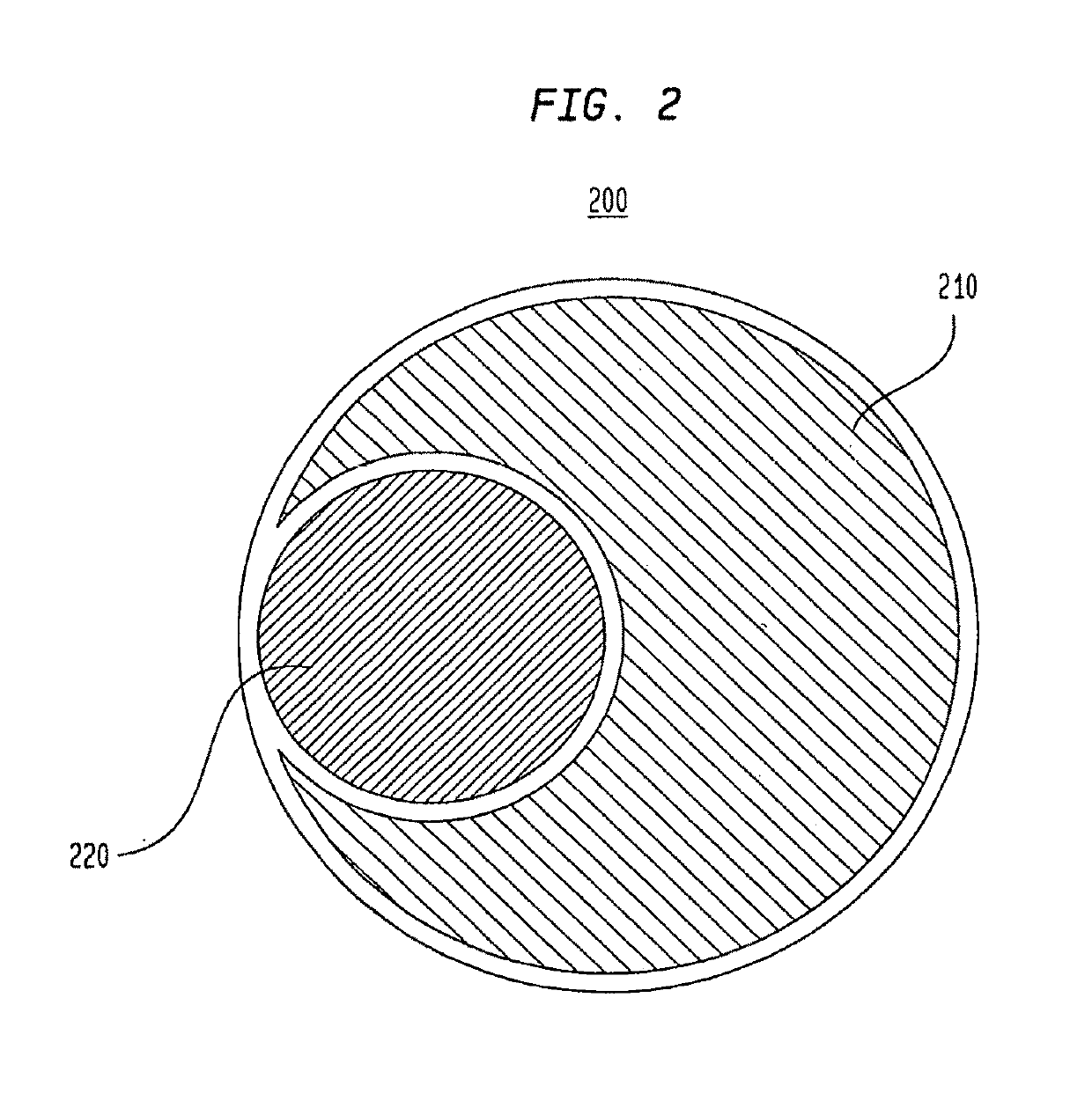
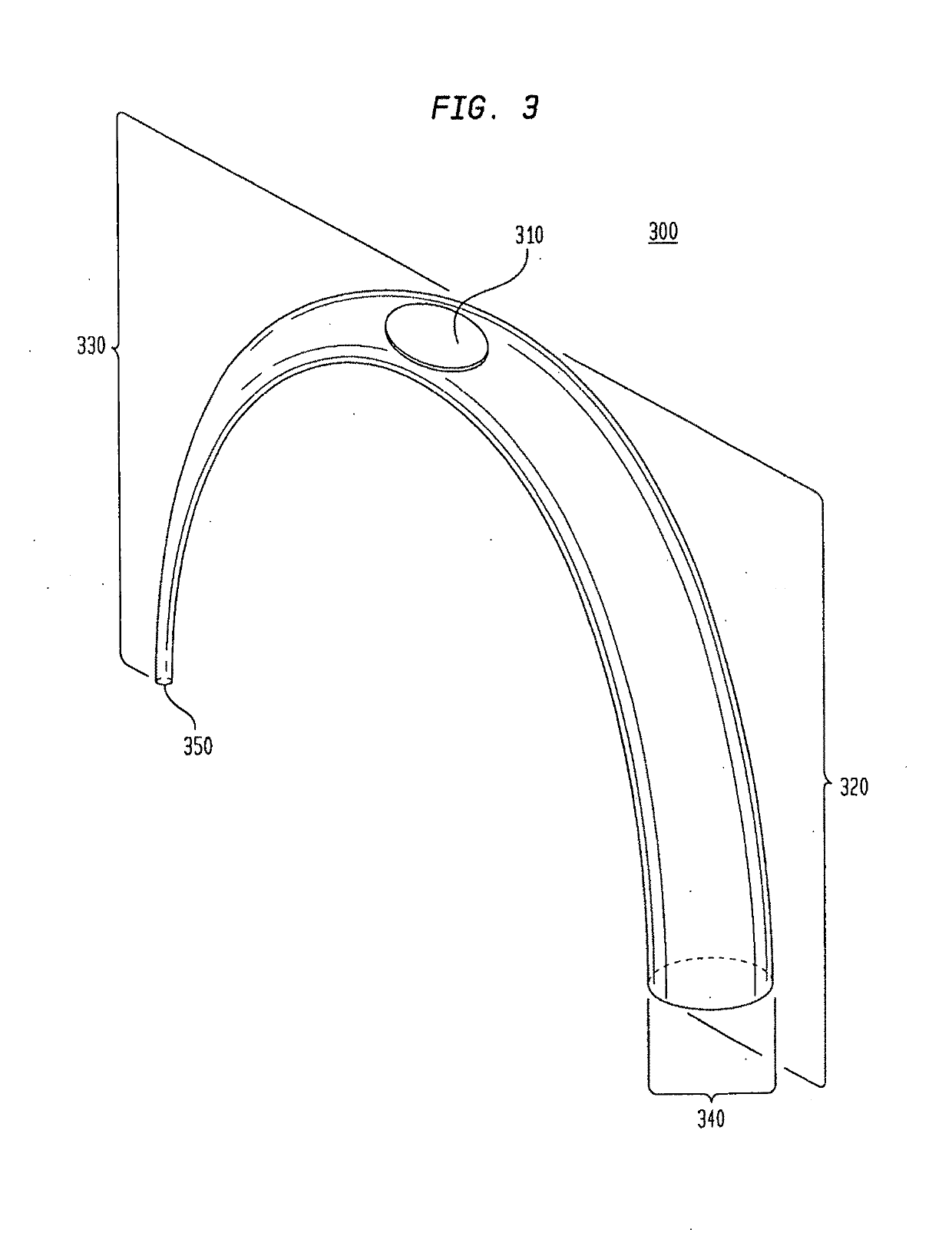
The invention is described as an endovascular device that is used in medical procedures such as angioplasty. The device has a tube with a first end that has a bifurcation, and a second end that has an opening. The bifurcation has two branches, which form a non-support lumen and a support lumen in the device. The non-support lumen allows for wire movement and communication between external attachment devices and the target area for treatment, while the support lumen provides stability and prevents kickback of the device. The device also has a side-hole that is symmetrical and uniform in perimeter. Overall, the invention improves the stability and maneuverability of the endovascular device during medical procedures.

Problems solved by technology

However, there is a general reluctance to puncture the right brachial artery due to the need to navigate through the innominate artery and arch and due to the risk for complications such as direct nerve trauma and ischemic occlusion resulting in long-term disability (Alvarez-Tostado J. A. et al.
Distal thrombectomy is a technically difficult procedure (Singh P. et al.
Despite good clinical outcome, limitations of this device include operator learning curve, the need to traverse the occluded artery to deploy the device distal to the occlusion, the duration required to perform multiple passes with device, clot fragmentation and passage of an embolus within the bloodstream (Meyers P. M. et al.
These stents are not ideal for treating intracranial disease due to their rigidity which makes navigation in the convoluted intracranial vessels difficult (Singh P. et al.
Drawbacks of this method include delayed in-stent thrombosis, the use of platelet inhibitors which may cause intracerebral hemorrhage (ICH) and perforator occlusion from relocation of the thrombus after stent placement (Samaniego E. A. et al Front Neurol.
These include the requirement for double anti-platelet medication, which potentially adds to the risk of hemorrhagic complications and the risk of in-stent thrombosis or stenosis.
Despite the potential to diminish procedure time and to improve recanalization rates, drawbacks to using these devices remain.
Although mechanical endovascular neurointerventions using a transfemoral approach are the current standard for the treatment of acute stroke, it is difficult to access the left internal carotid artery via these transfemoral techniques when an aortic arch variation occurs.
A similar transfemoral access problem can occur when vertebral arteries arise at an acute angle from the subclavian artery.
Although results have improved, repair of this abnormality is associated with a significant mortality and morbidity (Tchervenkov C. I. et al.
For example, the acute angle at which the left common carotid artery branches from the aortic arch in the bovine arch configuration makes mechanical endovascular neurointervention difficult, especially when additional tortuosity (i.e., twists) in the aorta and / or the carotid artery are present.
However, when a wire is advanced through these catheters in order to achieve distal access to the artery head, these catheters lack adequate support which results in kickback of the advancing wire into the aortic arch.
The lack of adequate support and the resulting kickback of the advancing wire make effective treatment impossible.
Even when catheterization is achieved in these situations, the process of arriving at the correct combination of catheters and wires results in long treatment delays.
In cases of acute stroke, long delays in obtaining access to arteries often leads to additional irreversible cell death with additional permanent neurologic injury.

Method used


Image

  • Vessel access catheter
  • Vessel access catheter
  • Vessel access catheter

Examples


Embodiment Construction

Glossary

[0104]The term “ablation” as used herein, refers to a procedure that uses radiofrequency energy (e.g., microwave heat) to destroy a small area of heart tissue that is causing rapid and irregular heartbeats. Destroying this tissue restores the heart's regular rhythm. The procedure is also called radiofrequency ablation.

[0105]The terms “acute angle” and “acute angulation” are used interchangeably herein to refer to a sharp, obstructive or abnormal angle or bend (e.g., less than 90 degrees) in an organ, artery, vessel, etc.

Anatomical Terms

[0106]When referring to animals that typically have one end with a head and mouth, with the opposite end often having the anus and tail, the head end is referred to as the cranial end, while the tail end is referred to as the caudal end. Within the head itself, rostral refers to the direction toward the end of the nose, and caudal is used to refer to the tail direction. The surface or side of an animal's body that is normally oriented upwards,...


PUM


Abstract

A medical device comprising a tube having first segment comprising a primary opening at the proximal end nearest an external termination device; and a second segment comprising a secondary opening at the distal end; and a side-hole dividing the first segment and the second segment, wherein the internal diameter of the first segment is greater than the internal diameter of the second segment, and the tube has no pre-formed curved configuration. The first segment extends from the primary opening to the side-hole and the second segment extends from the side-hole to the secondary opening. The side-hole and first segment form a non-support lumen, and the second segment forms a support lumen. The support lumen is effective to provide stability to the non-support lumen of the tube, to anchor the tube within an anchor area, and to prevent prolapse of the medical device elements due to a counterforce against the tube by the second device(s) being delivered through the tube to a more distal location of a target area; and to facilitate placement of the second medical device into the target area.A method of using the medical device described.

Description

CROSS-REFERENCE TO RELATED APPLICATIONS[0001]This application claims the benefit of priority to U.S. Non-Provisional application Ser. No. 15 / 250,693 filed Aug. 29, 2016, which in turn claims priority to Non-Provisional application Ser. No. 15 / 158,341 filed on May 18, 2016, the entire contents of which are incorporated by reference.FIELD OF THE INVENTION[0002]The described invention relates generally to endovascular devices.BACKGROUND OF THE INVENTIONBlood Vessel Structure and Function[0003]Blood vessels are dynamic structures that constrict, relax, pulsate, and proliferate. Within the body, blood vessels form a closed delivery system that begins and ends at the heart. There are three major types of blood vessels: (i) arteries; (ii) capillaries and (iii) veins. As the heart contracts, it forces blood into the large arteries leaving the ventricles. Blood then moves into smaller arteries successively, until finally reaching the smallest branches, the arterioles, which feed into the cap...

Claims


Application Information

Patent Timeline
IPC IPC(8): A61M25/10
CPCA61M25/10A61M2025/1061A61F2/958A61M2025/1052A61F2/82A61F2210/0014A61M2025/0063A61M2025/0175A61M25/007A61M25/0043A61B17/12136A61B17/1214A61B17/12181A61B17/12109A61B2017/1205A61B2017/22069A61B2017/00946A61B2017/00871A61B2017/22072A61B17/00
Inventor WALZMAN, DANIEL EZRA
Owner WALZMAN DANIEL EZRA
Learn More