
Method of wireless communication and user equipment

a wireless communication and user equipment technology, applied in the direction of digital transmission, electrical equipment, transmission path sub-channel allocation, etc., can solve the problems of reducing the original coverage of each rrh in the lower frequency band, diffraction losses as well as penetration losses are higher, and the loss of free space propagation is higher. , to achieve the effect of improving the resource management efficiency of an evolved nodeb

Inactive Publication Date: 2019-06-13
NTT DOCOMO INC
View PDF0 Cites 35 Cited by
  • Summary
  • Abstract
  • Description
  • Claims
  • Application Information

AI Technical Summary

Benefits of technology

The present invention provides a method for transmitting a Channel State Information Reference Signal (CSI-RS) that improves resource management efficiency of an evolved NodeB (eNB) or RRH with massive MIMO as well as the channel measurement efficiency of a user equipment (UE). It provides a solution for designing CSI-RS patterns for multiple virtual beam cells that share the same cell identification (ID) and improves the efficiency of resource utilization and signal measurement for UEs. This method uses non-overlapped (spatially orthogonal) virtual beam cells and divides them into different groups based on their overlapping (spatially non-orthogonal) characteristics. The virtual beam cells within a group are transmitting CSI-RS on the same CSI-RS resource element(s) (RE(s)). By identifying the unique beam pattern or beam index of each CSI-RS sharing the same REs, the method allows the network to easily detect and identify the corresponding virtual beam cell selected by a UE. This improves the efficiency of resource utilization and signal measurement for UEs.

Problems solved by technology

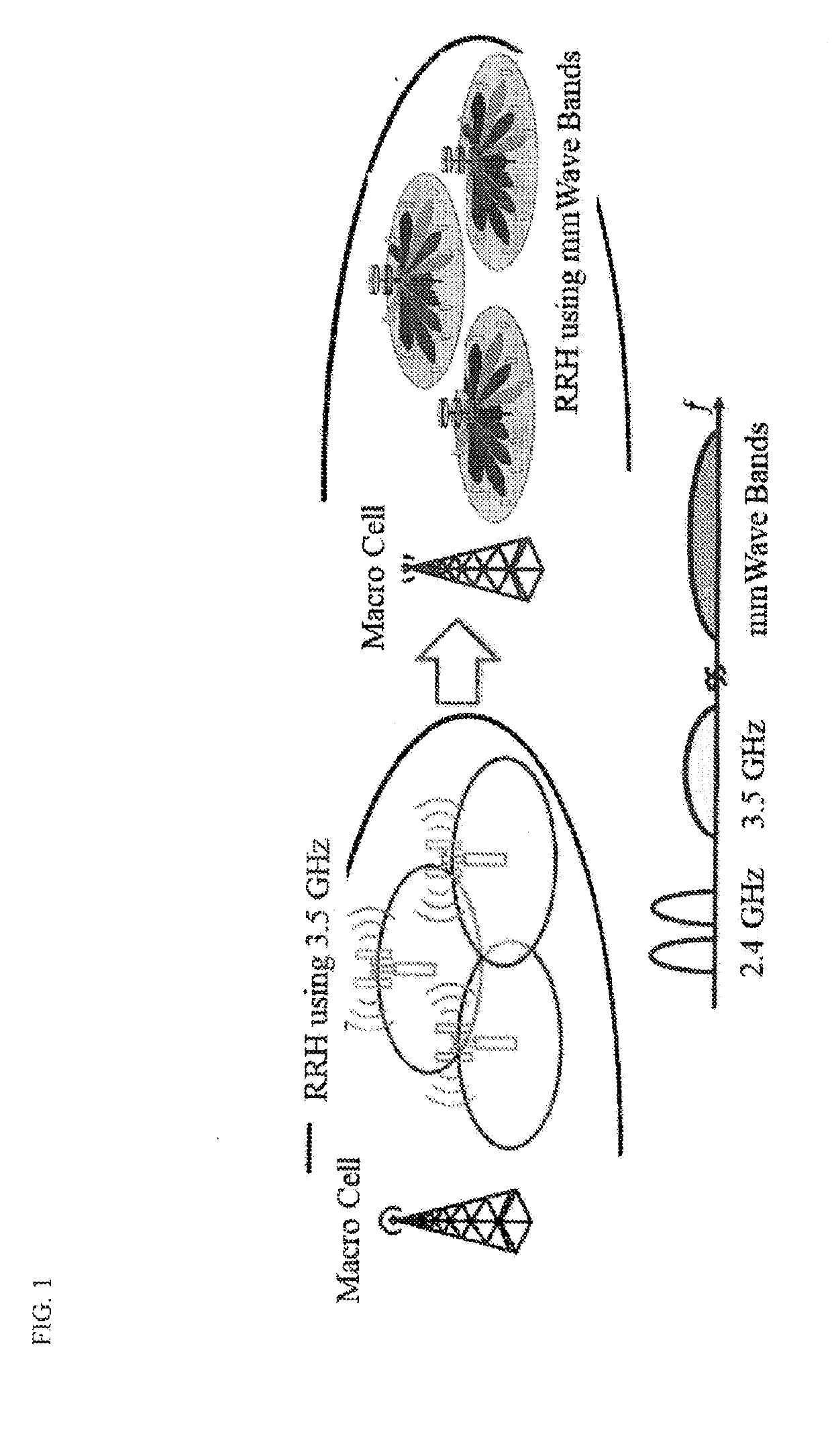
When the RRHs in the right figure are deployed in a New Radio (NR) system using the spectrum at higher carrier frequency, such as mmWave bands, the propagation is hostile and the free-space propagation loss is higher and the diffraction losses as well as the penetration losses are higher.
All these significant propagation losses will reduce the original coverage of each RRH in the lower frequency bands.
However, for a well-planned cellular network the operation, in the case that the cell location and cell coverage as well as the number of cells remain fixed, achieving similar gains with network densification (i.e., in cases where both the number of beams / cells increase and their coverage is configurable, is not possible with the current state-of-the-art methods.
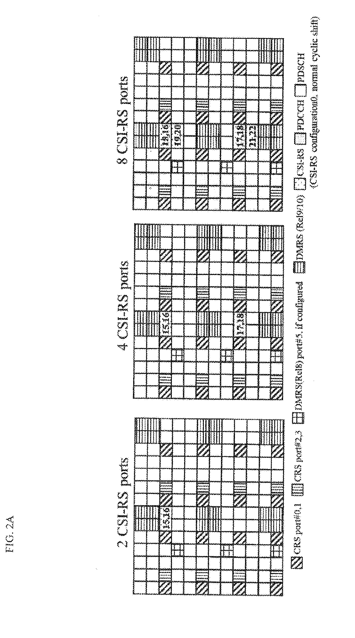
However, for the Massive MIMO communication systems, current LTE CSI-RS cannot to support the CSI-RS for a large number of beams / streams (>16 streams) on the limited resources (e.g., antenna ports).
Extending the antenna ports on orthogonal resources is not desirable, because it will sacrifice the resources for the data transmission, resulting in larger overhead and lower system throughput.

Method used


Image

  • Method of wireless communication and user equipment
  • Method of wireless communication and user equipment
  • Method of wireless communication and user equipment

Examples


first example

[0080](Beam-Specific CSI-RS Pattern Configuration)

[0081]According to one or more embodiments of a first example of the present invention, the BS 20 may generate a CSI-RS that is quasi-orthogonally or non-orthogonally multiplexed on multiple resource elements (REs) and transmit the CSI-RS to the UE 10. For example, different transmission power may be applied to the multiple REs on which the CSI-RS is multiplexed. For example, the BS 20 may notify the UE 10 of transmission power information that indicates values (level) of the applied different transmission power.

[0082]In one or more embodiments of the present invention, the resource element (RE) is referered to as a resource unit (RU) or a resource. For example, the REs mapped to the CSI-RS may be indicated as a CSI-RS REs or a CSI-RS RUs.

[0083]One or more embodiments of a first example of the present invention introduce the beam-specific CSI-RS pattern with different power level setting on the CSI-RS RUs as shown in FIGS. 6A-6C. One...

second example

[0209](Beam-Specific CSI-RS Pattern Configuration)

[0210]According to one or more embodiments of a second example of the present invention, the BS 20 may generate a CSI-RS that is quasi-orthogonally or non-orthogonally multiplexed on multiple REs and transmit the CSI-RS tot the UE 10. For example, the BS 20 may scramble the multiple REs on which the CSI-RS is multiplexed with a predetermined scrambling sequence. For example, the BS 20 may notify the UE 10 of scrambling sequence information that indicates the predetermined scrambling sequence.

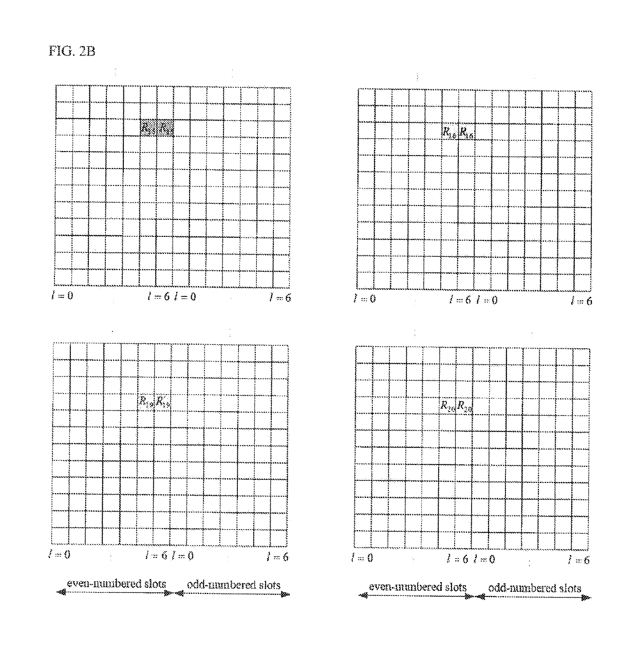
[0211]One or more embodiments of the second example of the present invention introduce the beam-specific CSI-RS pattern with different scrambling sequences. Assuming the basic CSI-RS sequence rl,n(m) is defined in Sect. 6.10.5.1 of TS36.211 as

rl,ns(m)=12(1-2·c(2m))+j12(1-2·c(2m+1)),m=0,1,…,NRBmax,DL-1

where ns is the slot number within a radio frame and l is the OFDM symbol number within the slot. The pseudo-random sequence c(i) is defined in Sect...


PUM


Abstract

A method for wireless communication includes transmitting, from a base station (BS) to a user equipment (UE), a Channel State Information Reference Signal (CSI-RS). The CSI RS is quasi-orthogonally or non-orthogonally multiplexed on multiple resource elements (REs). The BS transmits multiple CSI-RSs to the UE and the multiple CSI-RSs are multiplexed on a same RE. The method further includes applying, with the BS, different transmission power to the multiple REs, and notifying, with the BS, the UE of transmission power information that indicates values of the applied different transmission power. The method further includes scrambling, with the BS, the multiple REs with a predetermined scrambling sequence and notifying, with the BS, the UE of scrambling sequence information that indicates predetermined scrambling sequence.

Description

[0001]The present invention generally relates to a method of multiplexing downlink reference signal such as a Channel State Information-Reference Signal (CSI-RS) in a wireless communication system.BACKGROUND ART[0002]Dense cellular network deployments relying on the use of Massive Multi-Input-Multi-Output (MIMO) (M-MIMO) technology are becoming very attractive candidates for future radio access technologies. This is partly due to the promise of Massive MIMO for providing very large throughput increases per BS, due to its ability to multiplex a large number of high-rate streams over each transmission resource element.[0003]It is well accepted by now that major gains in the physical (PHY) layer in terms of throughput per unit area are to come from the judicious use of dense infrastructure antenna deployments, comprising of a dense network of small cells, possibly equipped with large antenna arrays. Indeed, Massive MIMO is very attractive when it is used over dense (small cell) deploym...

Claims


Application Information

Patent Timeline
Patent Type & Authority Applications(United States)
IPC IPC(8): H04L5/00
CPCH04L5/0048H04L5/0023H04L5/003H04L5/005
Inventor LIU, LEKAKISHIMA, YUICHIPAPADOPOULOS, HARALABOS
Owner NTT DOCOMO INC
Learn More