
Haptic Effects from Focused Acoustic Fields

a haptic effect and focused acoustic field technology, applied in the field of haptic effects, can solve the problems of increasing the cost of the device, requiring expensive and time-consuming solutions, and equally small distortions in the image data captured by the camera system

Active Publication Date: 2019-05-30
ULTRAHAPTICS IP LTD
View PDF7 Cites 16 Cited by
  • Summary
  • Abstract
  • Description
  • Claims
  • Application Information

AI Technical Summary

Benefits of technology

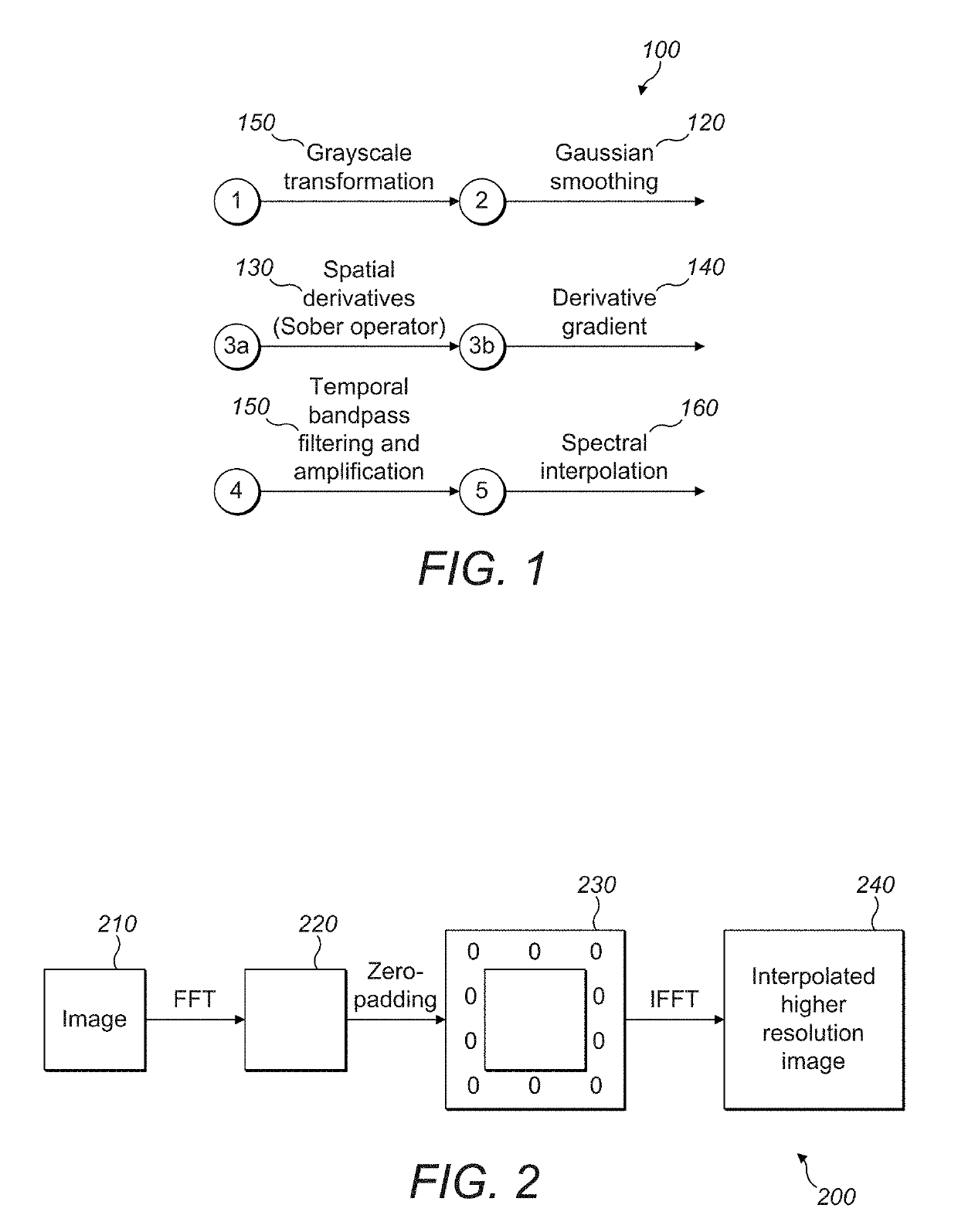
The patent describes a technology that uses sound waves to capture small movements in a camera. This technology uses a process called magnification to compare different sound waves and calibrate the camera. The technology also uses ultrasound to create haptic feedback without needing a battery or external device.

Problems solved by technology

While different standard calibration procedures can be adopted to find the relative position between the array and the RGB camera, they all involve some hardware challenges and / or require active human intervention to perform calibration.
Human intervention is difficult to achieve, and in the cases in which manual intervention is needed, makes for expensive and time-consuming solutions.
1) Microphones embedded in the camera, or positioned in its proximity, can be used to measure the acoustic field from the array. A minimum of three (or more) transducers at known array-referenced positions can be activated at different timings and the signals are received at the microphone. The signal can be a short pulse, chirp sine wave or modulated signal that encodes known points in time. Since the time-of-flight of more than 3 receivers is recorded, the problem becomes one of multilateration, a surveillance technique based on the measurement of the difference in distance to two stations at known locations by broadcast signals at known times. Weighted least squares optimization finds the minima of a cost function which consists of the sum of the squared residual, leading to the estimation of the relative position of the camera with respect to the array. Once the relative position of the camera is determined, a calibration of the system is obtained.
2) A minimum of three or more receivers embedded in the haptic array can record a signal from a transmitting transducer embedded in the camera or in its proximity. The signal can be a short pulse, chirp sine wave or modulated signal that encodes known points in time. Since the time-of-flight of more than three receivers is recorded, the problem becomes one of multilateration. Weighted least squares optimization finds the minima of a cost function which consists of the sum of the squared residual, leading to the estimation of the relative position of the camera with respect to the array. Once the relative position of the camera is determined, a calibration of the system is obtained.
3) One or more fiducial marks on the array, on its proximity or on the covering material, that are in each case visible to the camera can be captured optically. They can be a recognizable spot, or a distinguishable symbol. By comparing the frames acquired by the optical camera with an exemplar, it would be possible to compute the differences between the actual and the ideal position of the array with respect to the camera, and hence calibrate the system.
This results in equally small distortions in the image data captured by the camera system.
This increases the cost of the device.
Contrast-detection algorithms are common in mirrorless cameras and other applications where phase detection is either too expensive or too bulky to implement.
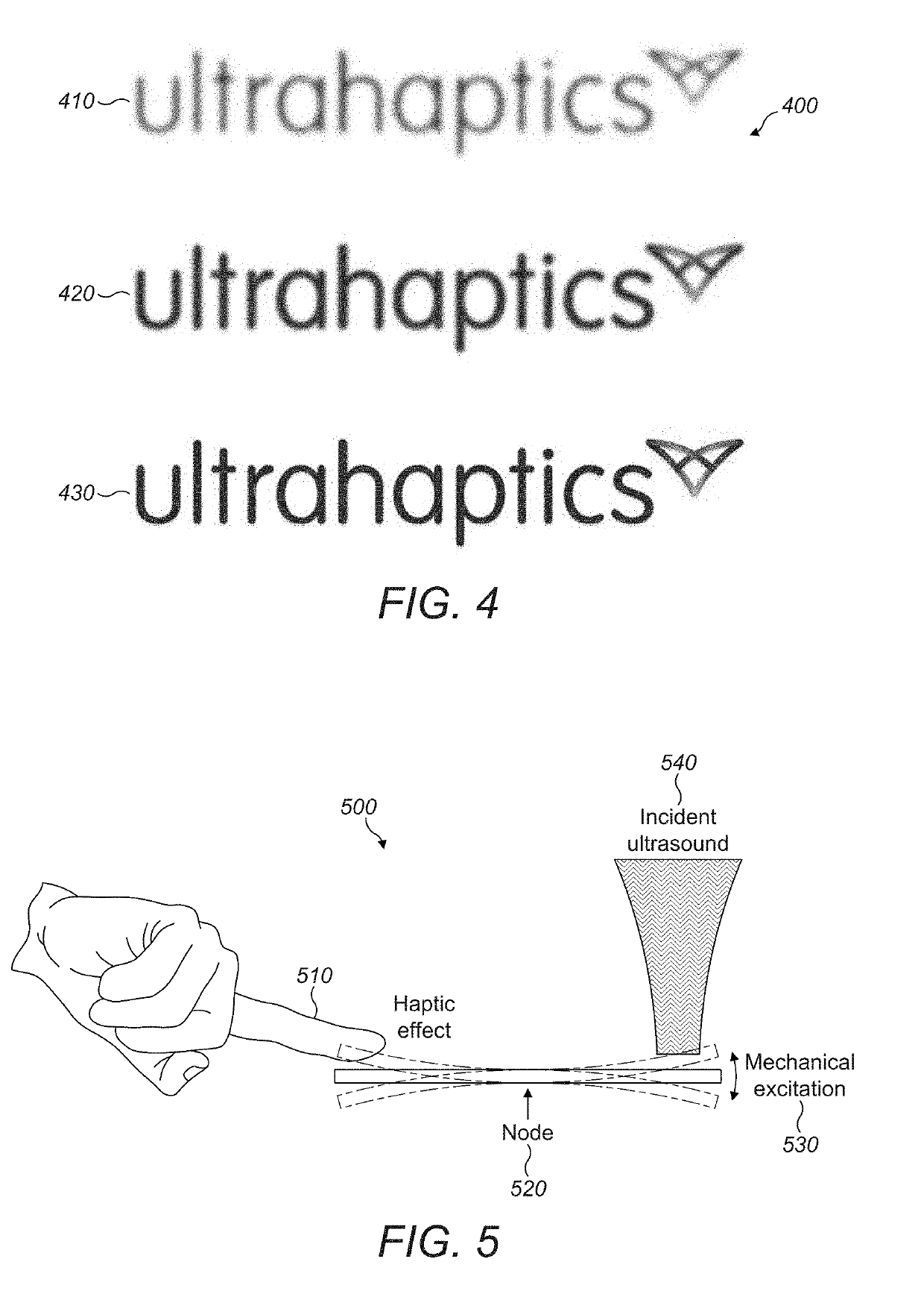
The haptic region is the area which is in contact with the user and is vibrating to give feedback to the user and is not necessarily always available for reception of ultrasound.
A large Q-factor (slow ring up and down) makes the device maximally sensitive to incident ultrasound but at the cost of precision—it will take more time to activate and deactivate the haptic.
A low-Q device can be very precise but will suffer from limited max amplitude when compared to the high-Q device.

Method used


Image

  • Haptic Effects from Focused Acoustic Fields
  • Haptic Effects from Focused Acoustic Fields
  • Haptic Effects from Focused Acoustic Fields

Examples


example form

[0079 factors include:[0080]A rod intended to emulate a pen or scalpel.[0081]A tube which is designed to have a stylus inserted.[0082]A larger tube or rod meant to emulate the size and shape the handle of a racket, golf club, or bat (as in FIG. 7).[0083]A glove with resonators placed in various places such as the back of the hand which are not as sensitive to traditional mid-air haptics.[0084]A face mask.[0085]A full-body suit with many different resonators matched to the specific locations on the body.[0086]A game piece, figurine, model, or toy.

[0087]Further description of these embodiments may be as follows:

[0088]1. A method to provide haptic feedback comprising:

a. A device with at least one mechanical resonance frequency;

b. A receive surface designed to receive acoustic energy modulated at that frequency;

c. Once acoustic energy is received, vibrates at another location on the device; and

d. This second (haptic) location can be in contact with a user to provide haptic feedback.

[008...


PUM


Abstract

To resolve an issue related to the calibration of optical cameras in transducer-based mid-air haptic systems, the magnification of the motion induced on an optical camera by an acoustic field modulated at specific frequencies reveals very small temporal variations in video frames. This quantized distortion is used to compare different acoustic fields and to solve the calibration problem in an automatized manner. Further, mechanical resonators may be excited by ultrasound when it is modulated at the resonant frequency. When enough energy is transferred and when operating at the correct frequency, a user in contact with the device can feel vibration near areas of largest displacement. This effect can be exploited to create devices which can produce haptic feedback while not carrying a battery or exciter when in the presence of an ultrasonic source.

Description

RELATED APPLICATIONS[0001]This application claims the benefit of the following two U.S. Provisional Patent Applications, all of which are incorporated by reference in their entirety:[0002]1) Ser. No. 62 / 590,609, filed Nov. 26, 2017; and[0003]2) Ser. No. 62 / 691,130, filed Jun. 28, 2018.FIELD OF THE DISCLOSURE[0004]The present disclosure relates generally to acoustically-driven haptic effects in mid-air haptic systems.BACKGROUND[0005]A continuous distribution of sound energy, referred to as an “acoustic field”, may be used for a range of applications including haptic feedback in mid-air.[0006]In most applications, haptic feedback is generated by an array of transducers, and a user's gesture is recognized by means of an optical camera. By identifying the user's gesture and focusing the acoustic field onto the user, an action is performed and a specific haptic feedback may be provided as a response. Consider an in-vehicle gesture system as an example scenario. In this application, the a...

Claims


Application Information

Patent Timeline
Patent Type & Authority Applications(United States)
IPC IPC(8): G06F3/01G06F3/0354
CPCG06F3/016G06F3/03545G06F3/017G06F3/0304G06F3/038G10K11/34
Inventor IODICE, MICHELEKAPPUS, BRIANCARTER, BENJAMIN JOHN OLIVERWREN, WILLIAM
Owner ULTRAHAPTICS IP LTD
Learn More