
Controllable power and lighting system

a controllable power and lighting technology, applied in the direction of coupling device connection, lighting and heating apparatus, agriculture, etc., can solve the problems of increased risk of dc voltage drop, increased distance between ac/dc inverters, and increased inverter costs

Active Publication Date: 2019-03-21
INTELLIGENT GROWTH SOLUTIONS LTD
View PDF5 Cites 8 Cited by
  • Summary
  • Abstract
  • Description
  • Claims
  • Application Information

AI Technical Summary

Benefits of technology

The patent text describes a new lighting system that uses LED lights powered by a 3-phase AC power supply. This system is more efficient and cost-effective than traditional lighting systems. The use of a 3-phase AC power supply allows for the use of smaller capacitors and inductive components, resulting in improved power factor and reduced harmonic distortion. The system also addresses the issue of hot neutrals and tripping single fuses, which can occur when using a single phase AC power supply. Overall, this new system provides improved safety and reliability for large-scale installations.

Problems solved by technology

A particular disadvantage of using LED-based lighting for the provision of lighting for large-scale commercial or industrial applications, or high intensity lighting systems which require high numbers of LED lights, is that the necessary spacing between either the individual LED lights or between groups of the LED lights means that the distance between the AC / DC inverters needs to increase because such arrangements typically mean that the risk of DC voltage drop is increased.
In addition to the LED costs indicated hereinbefore, and the additional inverter costs, such modified systems require far higher quantities of high voltage AC wiring, to connect to multiple inverters, than would be required if using a single large AC / DC inverter.
This is particularly expensive in large-scale commercial systems, such as systems for use in large-scale industrial applications or complex commercial applications where all wiring and inverters must be IP rated.
In addition, the complexity of such systems means that the measures required for controlling the LED lighting within such modified systems, as well as the measurement of wavelength, intensity and photoperiod generated becomes impractical as well as potentially hazardous should any fault occur.
Given the ever-increasing awareness of both domestic and commercial consumers of the environmental cost associated with wasted energy consumption, the relative inefficiency of the power conversion provided by commercially available LED arrays can be a deterrent to their use in some circumstances.

Method used


Image

  • Controllable power and lighting system
  • Controllable power and lighting system
  • Controllable power and lighting system

Examples


example 1

ion Tree at Low Voltage, 3-Phase, AC and High Currents

[0514]Taking the greenhouse system illustrated in FIG. 21 use of a large AC to AC transformer of 10 kw (Kilowatt) capacity and an LED array as defined hereinbefore provides sufficient heat and light for coverage of a growing area of from about 100 m2 to about 200 m2. Use of a lower capacity, 4 kw AC to AC transformer with an LED array as defined hereinbefore would correspondingly provide heating and lighting for a smaller greenhouse having a growing area of from about 40 m2 to about 80 m2.

[0515]Using tubular aluminium bus bars, the AC-to-AC transformer could be increased to 150 kW or larger. This would provide sufficient power for larger growing areas of from 1,500 m2 to 3,000 m2.

example 2

ble Power and Lighting System

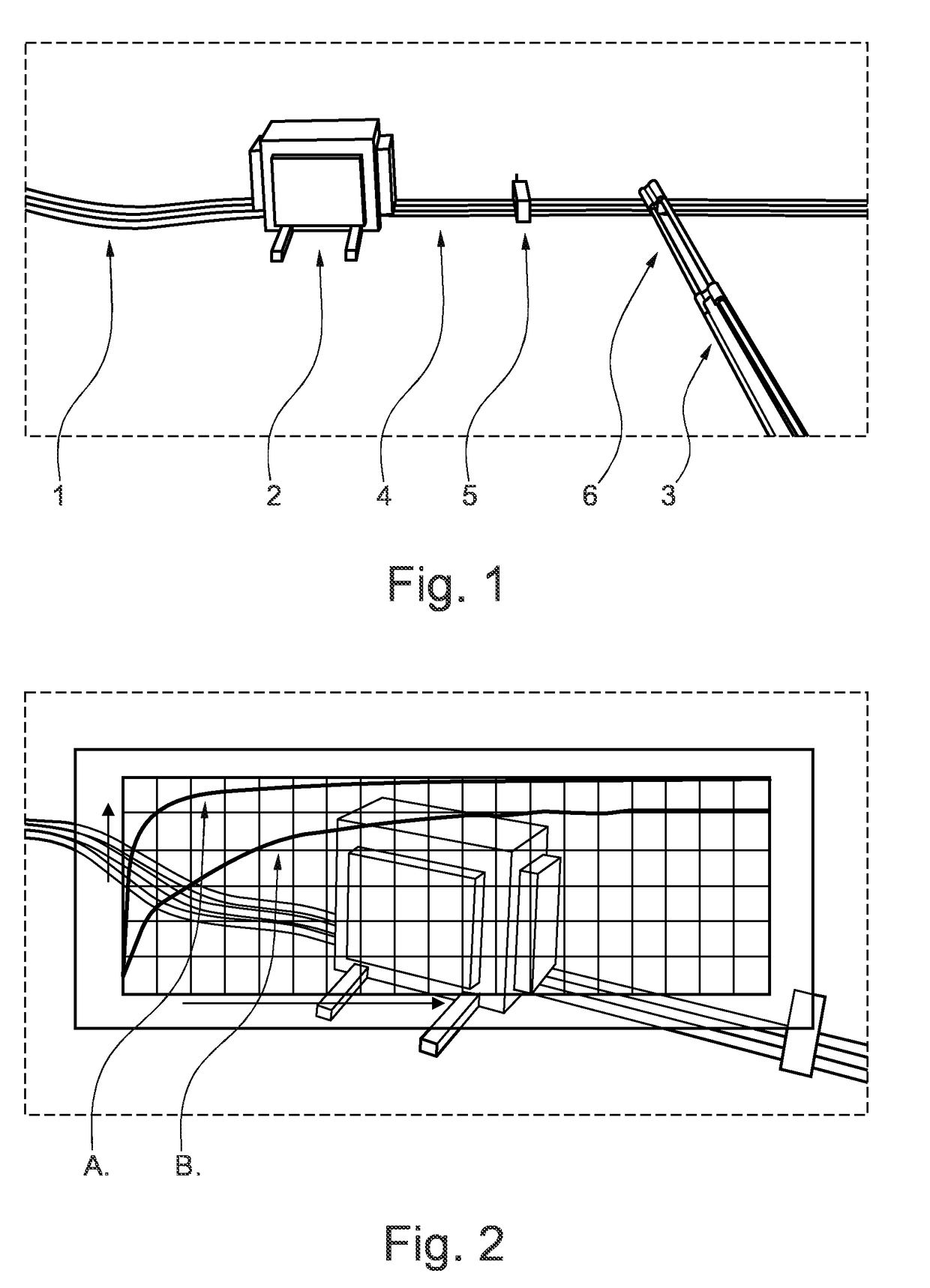
[0518]The system illustrated in FIG. 1 is an implemented controllable power and lighting system in accordance with the present disclosure. This system includes an input 3-phase AC power supply, voltage step-down means, and distribution of power to a lighting device where 3-phase AC / DC rectification occurs. Although only a partial representation of an exemplary lighting system is illustrated in FIG. 1, any suitable power transformation and rectification means illustrated and as discussed in the present description can be readily applied to power a wide variety of different lighting devices, as well as non-lighting devices from such an arrangement. In this specific system segment the power is advantageously distributed to the lighting device via conductive bus bars. As will be also appreciated from the foregoing description, alternative conductive means can also be used to distribute power to the one or more lighting, or non-lighting devices in such system...


PUM


Abstract

There is provided herein controllable power and lighting system. There is particularly provided a method for the arrangement and automatic control of one or more power consuming devices, including one or more light emitting diode (LED)-containing lighting devices, and optionally one or more non-LED based devices, wherein the devices are adapted to be powered by 3-phase AC power within the present systems.

Description

FIELD OF THE INVENTION[0001]The present disclosure relates to a novel controllable power and lighting system. The disclosure particularly relates to a method for the arrangement and automatic control of one or more power consuming devices, wherein at least one of the power consuming devices is a light emitting diode (LED)-containing lighting device, within the present system, wherein the LED-containing lighting device is adapted to be powered by 3-phase and wherein the 3-phase AC power supplied to the system is converted to DC power via 3-phase AC / DC rectification, and particularly to such arrangements where the 3-phase AC power is distributed on conductive bus bars. The disclosure also relates to a method for the arrangement and automatic control of lighting devices within the present system, particularly light emitting diode (LED) lights, and optionally non-LED based devices, adapted to be powered by 3-phase AC power where the 3-phase AC power is distributed via conventional wirin...

Claims


Application Information

Patent Timeline
IPC IPC(8): H05B37/02H05B33/08F21S4/28H01R25/14H05B44/00
CPCH05B37/0263H05B33/0866H05B33/0809H05B37/0272F21S4/28H01R25/147H05B45/3725H05B47/19A01G9/249H05B45/37H05B45/24H05B47/185
Inventor AYKROYD, HENRYSCOTT, DAVID
Owner INTELLIGENT GROWTH SOLUTIONS LTD
Learn More