Three-dimensional distance measurement apparatus
a technology of distance measurement and three-dimensional distance, applied in the direction of instruments, image analysis, computing, etc., can solve the problems of weak light returning to the distance measurement equipment, difficult to accurately perform measurement, and difficult to normally measure distance, etc., to achieve the effect of suppressing the degradation of accuracy
- Summary
- Abstract
- Description
- Claims
- Application Information
AI Technical Summary
Benefits of technology
Problems solved by technology
Method used
Image
Examples
first embodiment
[0036]In the first embodiment, a plurality of light sources are individually turned on to change irradiation areas for a subject.
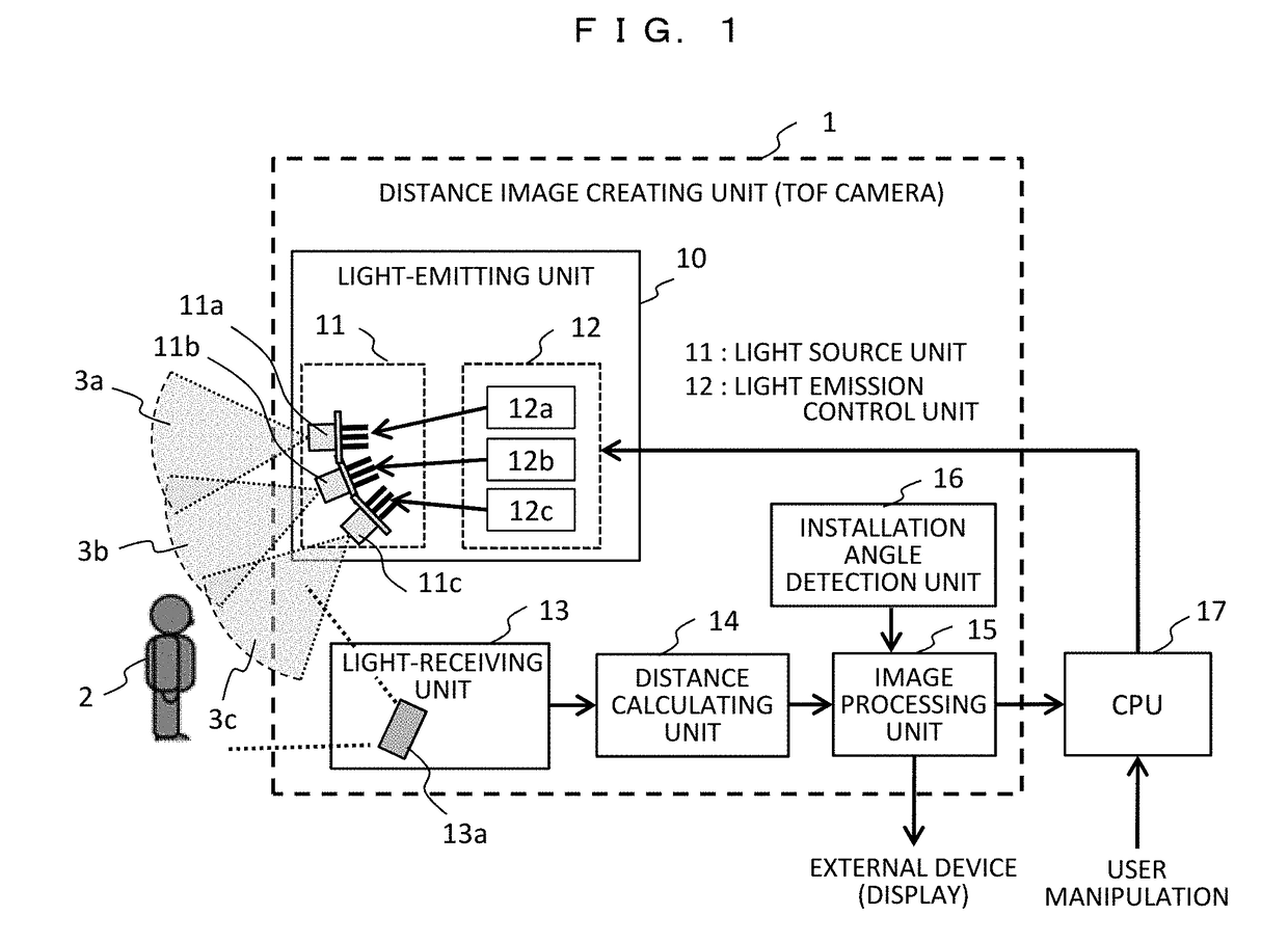
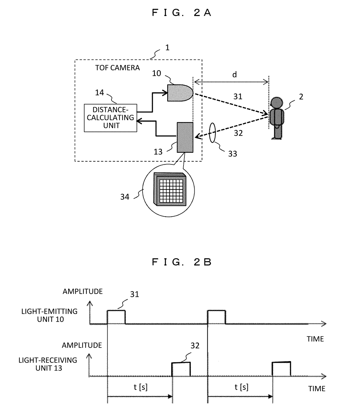
[0037]FIG. 1 is a block diagram illustrating a three-dimensional distance measurement apparatus according to the first embodiment. In the following example, it is assumed that a position of a person as a subject is detected. The three-dimensional distance measurement apparatus measures a distance to the subject including a person using a time-of-flight (TOF) method, and the distances to each part of the subject are displayed, for example, with different colors so as to output a distance image. In the three-dimensional distance measurement apparatus, a central processing unit (CPU) 17 controls a distance image creation unit 1 (hereinafter, referred to as a TOF camera) that creates a distance image on the basis of the TOF method.
[0038]The TOF camera 1 has a light-emitting unit 10 having a laser diode (LD) or a light-emitting diode (LED) that irradiates pulse...
second embodiment
[0075]Next, a three-dimensional distance measurement apparatus according to a second embodiment will be described. In the second embodiment, the laser light sources are configured to individually adjust the emitted light amount. A basic configuration of the apparatus is similar to that of the first embodiment (FIG. 1), and it will not be described repeatedly here.
[0076]A relationship between turn-on states of the laser light sources and the irradiated light amount distributions will be described with reference to FIGS. 10A, 10B, 11A, and 11B. FIGS. 10A and 10B illustrate a case where all of the three laser light sources are turned on with the same light amount. FIG. 10A illustrates the irradiation areas, and FIG. 10B illustrates the irradiated light amount distributions across the cross section A-A′. Assuming that the three irradiation areas 3a, 3b, and 3c have irradiated light amount distributions 50a, 50b, and 50c, respectively, and maximum irradiated light amounts La, Lb, and Lc,...
PUM
 Abstract
Description
Claims
Application Information
 - R&D
- Intellectual Property
- Life Sciences
- Materials
- Tech Scout
- Unparalleled Data Quality
- Higher Quality Content
- 60% Fewer Hallucinations
Browse by: Latest US Patents, China's latest patents, Technical Efficacy Thesaurus, Application Domain, Technology Topic, Popular Technical Reports.
© 2025 PatSnap. All rights reserved.Legal|Privacy policy|Modern Slavery Act Transparency Statement|Sitemap|About US| Contact US: help@patsnap.com


