
Flow divider jet-intensifier

a flow divider and jet-intensifier technology, applied in the direction of spraying apparatus, spray nozzle, movable spraying apparatus, etc., can solve problems such as flow interruption, and achieve the effects of strong cutting action, no hampered cutting or cleaning action, and substantially improved cleaning, cutting and boring performan

Active Publication Date: 2018-12-20
WV JET DRILLING LLC +1
View PDF1 Cites 1 Cited by
  • Summary
  • Abstract
  • Description
  • Claims
  • Application Information

AI Technical Summary

Benefits of technology

The present invention is a flow insert and improved flow tube that creates an interrupted flow pattern in the water, resulting in an intensified jet. This pattern helps improve cleaning, cutting, and boring performance by facilitating the removal of debris and other materials that may obstruct the cutting or cleaning action. The interruption in the flow is caused by rotating balls in the tube. This technology can be used in a variety of industrial applications such as cleaning, surface preparation, cutting, and boring / drilling.

Problems solved by technology

One or more balls circumferentially rotating around a ball-track assembly having a track support within the flow tube causes the flow interruption.

Method used


Image

  • Flow divider jet-intensifier
  • Flow divider jet-intensifier
  • Flow divider jet-intensifier

Examples


Embodiment Construction

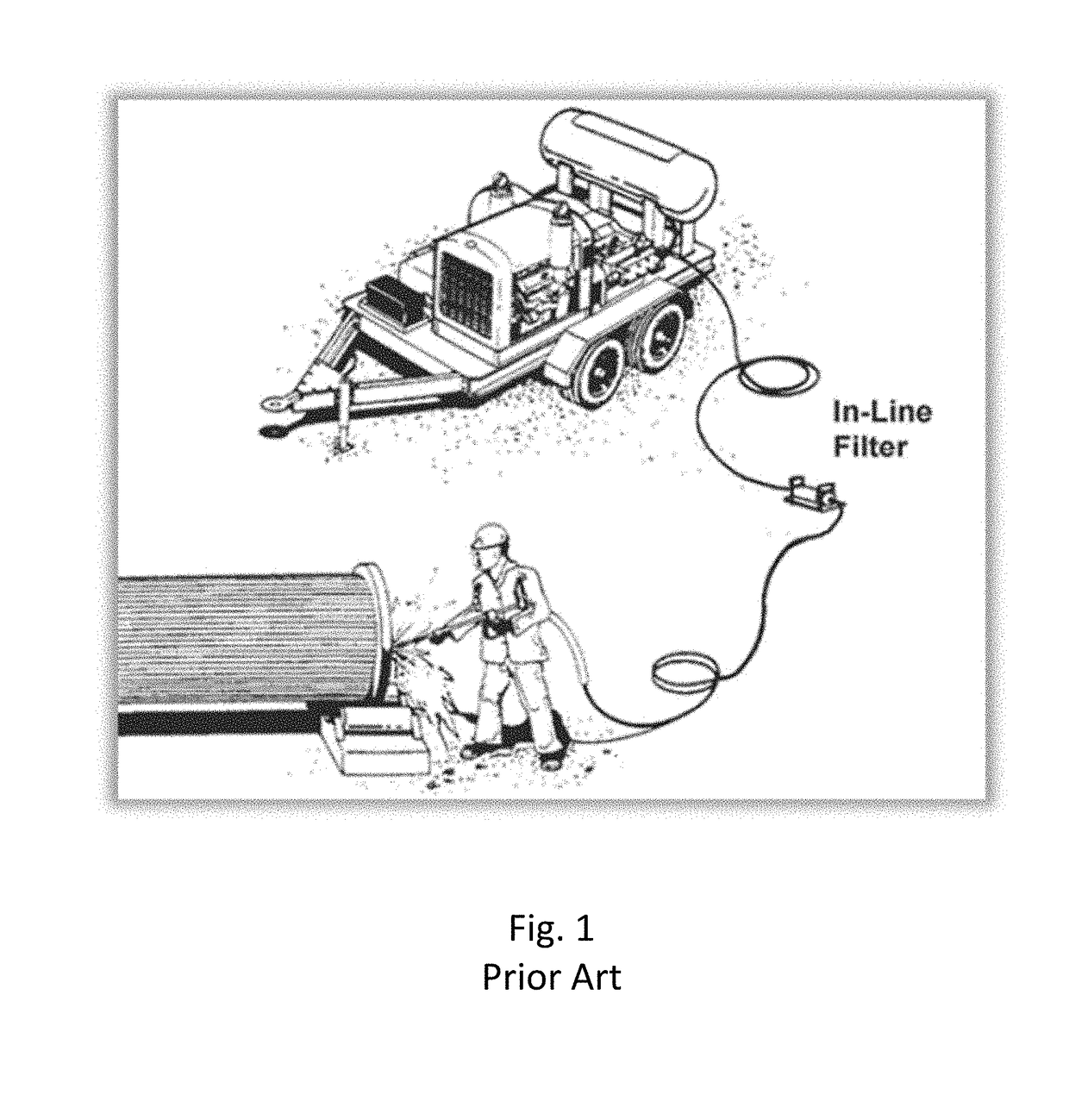
[0032]The Figures described above and the written description of specific structures and functions below are not presented to limit the scope of what Applicant has invented or the scope of the appended claims. Rather, the Figures and written description are provided to teach any person skilled in the art to make and use the inventions for which patent protection is sought. Those skilled in the art will appreciate that not all features of a commercial embodiment of the inventions are described or shown for the sake of clarity and understanding. Persons of skill in this art will also appreciate that the development of an actual commercial embodiment incorporating aspects of the present disclosure will require numerous implementation-specific decisions to achieve the developer's ultimate goal for the commercial embodiment. Such implementation-specific decisions may include, and likely are not limited to, compliance with system-related, business-related, government-related, and other co...


PUM


Abstract

The present invention provides a flow insert and improved flow tube, such as a nozzle, that divides flow by generating an interrupted flow pattern, including pressure / energy gradients, in the otherwise uninterrupted flow of high pressure water through the nozzle. Cutting, cleaning, and boring performance is substantially improved. The interrupted flow pattern can provide for egress of cut or broken material to get out of the way, so cutting or cleaning action is not hampered by a continuous flow of high-pressure water. One or more balls circumferentially rotating around a ball-track assembly having a track support within the flow tube causes the flow interruption. When the flow is interrupted, the interruption's trailing edge (that is, the flow's restarting edge after the interruption) provides stronger cutting action than a continuous solid jet. The flow tube can be used for a broad array of industrial cleaning, surface preparation, cutting, and boring / drilling applications.

Description

CROSS REFERENCE TO RELATED APPLICATIONS[0001]This application claims the benefit of U.S. Provisional Appl. No. 62 / 603,918, filed Jun. 16, 2017, entitled “Swirling Vortex Jet”, and U.S. Provisional Appl. No. 62 / 606,595, filed Oct. 2, 2017, entitled “Flow Divider Jet-Intensifier”.STATEMENT REGARDING FEDERALLY SPONSORED RESEARCH OR DEVELOPMENT[0002]Not applicable.REFERENCE TO APPENDIX[0003]Not applicable.BACKGROUND OF THE INVENTIONField of the Invention[0004]The disclosure generally relates to high-pressure flow tubes, such as nozzles, through which pressurized fluids flow. More particularly, the disclosure relates to high-pressure flow tubes using pressurized fluids for impacting surfaces, such as for cleaning surfaces or boring through surfaces.Description of the Related Art[0005]High-pressure waterjets and related equipment serve a broad array of industrial cleaning, surface preparation, cutting, and boring / drilling applications. These applications require a wide variety of tools an...

Claims


Application Information

Patent Timeline
Patent Type & Authority Applications(United States)
IPC IPC(8): B05B1/08
CPCB05B1/083B05B3/0404
Inventor PEARL, ZACHARY D.
Owner WV JET DRILLING LLC
Learn More