Eureka AIR delivers breakthrough ideas for toughest innovation challenges, trusted by R&D personnel around the world.

Amplified Photodegradation of Hydrogels and Methods of Producing the Same

Active Publication Date: 2018-12-20
UNIV OF COLORADO THE REGENTS OF
View PDF0 Cites 1 Cited by
  • Summary
  • Abstract
  • Description
  • Claims
  • Application Information

AI Technical Summary

Benefits of technology

The patent text describes a method for creating hydrogels that can contain cells and provide a uniform environment for cell survival. The cells can be evenly distributed throughout the hydrogel or layered within it, and the conditions under which cells are encapsulated can be altered to maximize cell viability. The use of bicompatible polymers that are biodegradable or can be susceptible to saccharide degradation is preferred. The size, shape, and vascularization of the hydrogel scaffold can also influence tissue structure and function, and synthetic polymers can be produced consistently in large quantities without the use of fillers or additives.

Problems solved by technology

Along these lines, tissue engineering applications require structures composed of varying degrees of thickness and size, which can affect tissue durability.

Method used


Image

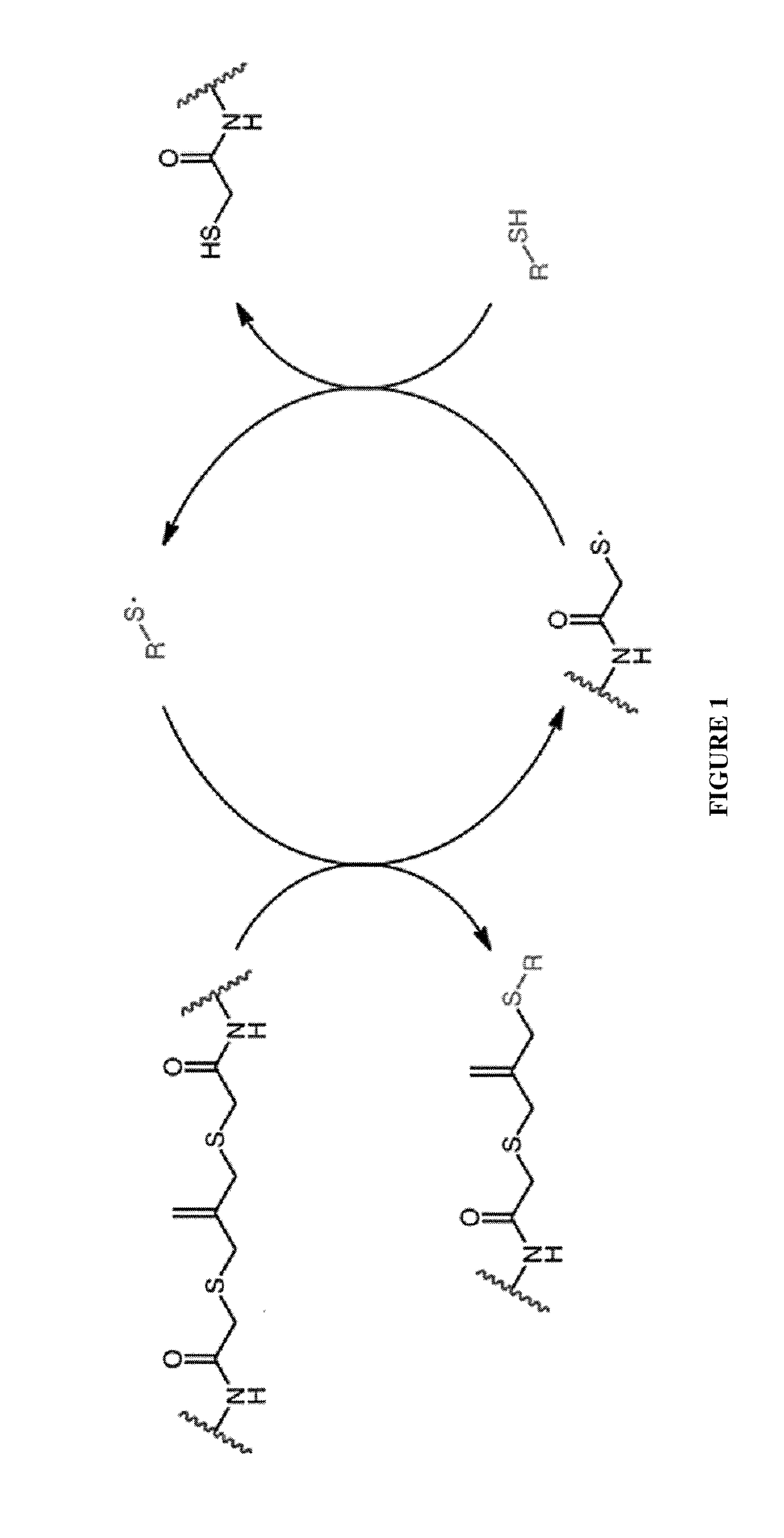
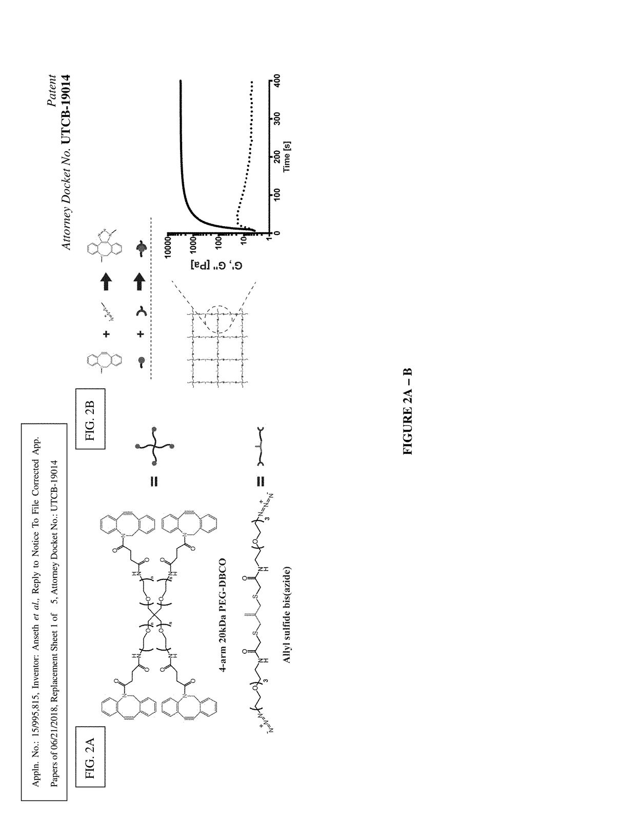
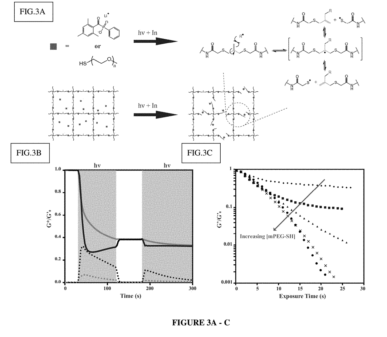
  • Amplified Photodegradation of Hydrogels and Methods of Producing the Same
  • Amplified Photodegradation of Hydrogels and Methods of Producing the Same
  • Amplified Photodegradation of Hydrogels and Methods of Producing the Same

Examples


example 1

Synthesis of Compound 1 [allyl sulfide bis(methyl ester)]

[0093]

[0094]Sodium (1.1 g, 48 mmol) was added to a flame dried flask charged with 150 mL anhydrous methanol and allowed to react for 10 minutes. After dissolution of the sodium, methyl thioglycolate (3.93 mL, 44 mmol) was added to the flask and the mixture was heated to reflux under an argon atmosphere and reacted for 20 minutes. 3-chloro-2-chloromethyl-1-propene (2.31 mL, 20 mmol) dissolved in 20 mL anhydrous methanol was then added dropwise to the reaction vessel over 45 minutes. The reaction mixture was purged with argon and stirred for 18 h at 60° C. The resulting mixture was filtered and concentrated through rotary evaporation to yield a yellow crude oil. The crude oil was taken up in 100 mL MQ water and extracted 6× with 100 mL diethyl ether (Et2O). The combined organic phases were washed with 200 mL brine, dried over sodium sulfate and concentrated by rotary evaporation to yield a pale yellow oil (2.88 g, 55%). TLC in 8...

example 2

Synthesis of Compound 2 [allyl sulfide bis(acetic acid)]

[0095]

[0096]100 ml of 1M LiOH (aq) was added to a solution of 1 (2.88 g, 10.9 mmol) in 100 ml THF on ice. The turbid solution was stirred for 5 h on ice, after which the solution was acidified (to pH=0) by addition of ˜100 mL 2M HCl. 50 ml brine was added and the solution was extracted with EtOAc (4×125 ml). The combined organics were dried over Na2SO4 and concentrated to yield a dark brown oil (2.57 g, 100%)

[0097]1H NMR (400 MHz, DMSO-d6) δ 12.58 (s, 2H), 5.04 (s, 2H), 3.32 (d, J=0.8 Hz, 4H), 3.14 (s, 4H).

example 3

Synthesis of Compound 3 [allyl sulfide bis(PEG3-azide)]

[0098]

[0099]A flame dried RBF was charged with 2 (360 mg, 1.53 mmol), diisopropylethylamine (DIEA, Sigma) (2.7 mL, 15.3 mmol), O-(7-Azabenzotriazol-1-yl)-N,N,N′,N′-tetramethyluronium hexafluorophosphate (HATU, Chem-Impex Int'l) (1.16 g, 3.05 mmol), and 250 mL ethyl acetate. The resulting slurry was purged with argon and reacted for 1 hr at room temperature. 11-Azido-3,6,9-trioxaundecan-1-amine (TCI America) (1 g, 4.58 mmol) was added to the flask and the mixture was stirred overnight at room temperature under an argon atmosphere. The resulting mixture was vacuum filtered and washed with 1N HCl (1×250 mL), saturated aq. sodium bicarbonate (1×250 mL), water (1×100 mL), and brine (1×100 mL). The organic phase was dried over sodium sulfate and concentrated to yield a dark yellow oil (646 mg, 66%). TLC in 80% acetone:20% hexanes revealed a single spot at Rf=0.3 with b staining.

[0100]1H NMR (400 MHz, Methanol-d4) δ 5.12 (s, 2H), 4.66 ...


PUM


Abstract

This invention is in the field of synthesis and amplified photodegradation of hydrogel network and methods of producing and using the same.

Description

CROSS-REFERENCE TO RELATED APPLICATIONS[0001]The present application claims the benefit of U.S. Provisional Patent Application No. 62 / 520,255, filed on Jun. 15, 2017, which is incorporated herein by reference.STATEMENT OF GOVERNMENTAL SUPPORT[0002]This invention was made with government support under grant numbers T32 GM065103 awarded by the National Institutes of Health and DMR 1408955 awarded by the National Science Foundation. The government has certain rights in the invention.FIELD OF THE INVENTION[0003]This invention is in the field of synthesis and amplified photodegradation of hydrogel networks and methods of producing and using the same.BACKGROUND OF THE INVENTION[0004]Biological scaffolds are natural or artificial structures capable of facilitating a variety of physiological processes. Such scaffolds can be formed in situ or in vitro as prefabricated matrices defined by a specific shape or structure. These scaffolds serve multiple purposes, such as, supporting cell or tissu...

Claims


Application Information

Patent Timeline
IPC IPC(8): A61L26/00
CPCA61L26/008A61L26/0057A61L26/0019A61L2300/62A61L2300/64C08L71/02C08K5/5313C08J3/075A61L27/52C08J2371/02
Inventor ANSETH, KRISTIMAROZAS, IANBROWN, TOBIN
Owner UNIV OF COLORADO THE REGENTS OF
Why Eureka
Eureka Blog
Learn More