Vehicle lamp

Inactive Publication Date: 2015-10-01
HONDA MOTOR CO LTD
View PDF2 Cites 6 Cited by
  • Summary
  • Abstract
  • Description
  • Claims
  • Application Information

AI Technical Summary

Benefits of technology

The present invention provides a vehicle lamp with a simpler mechanism for adjusting the optical axis. The lamp includes multiple light sources, with the first light sources being the main sources and the second light sources being the subordinate sources. The second light sources produce less light than the main sources, and only the optical axis of the first light sources can be adjusted. This saves time and effort in adjusting the optical axes of the second light sources. Additionally, the light guide member does not need to be shaped to match the shape of the reflector, which provides more flexibility in designing the vehicle lamp. A light shielding body is also included to adjust the irradiation area of the second light sources. The first and second light sources are arranged in a way that allows for easy adjustment of the optical axes of the first and high beam light sources.

Problems solved by technology

As a result, there is no flexibility in laying out each light source, making it likely that a vehicle lamp may be restricted in design.

Method used


Image

  • Vehicle lamp
  • Vehicle lamp
  • Vehicle lamp

Examples


Embodiment Construction

[0027]A detailed description will be given below of the vehicle lamp according to the present invention by citing a preferred embodiment and by referring to the accompanying drawings.

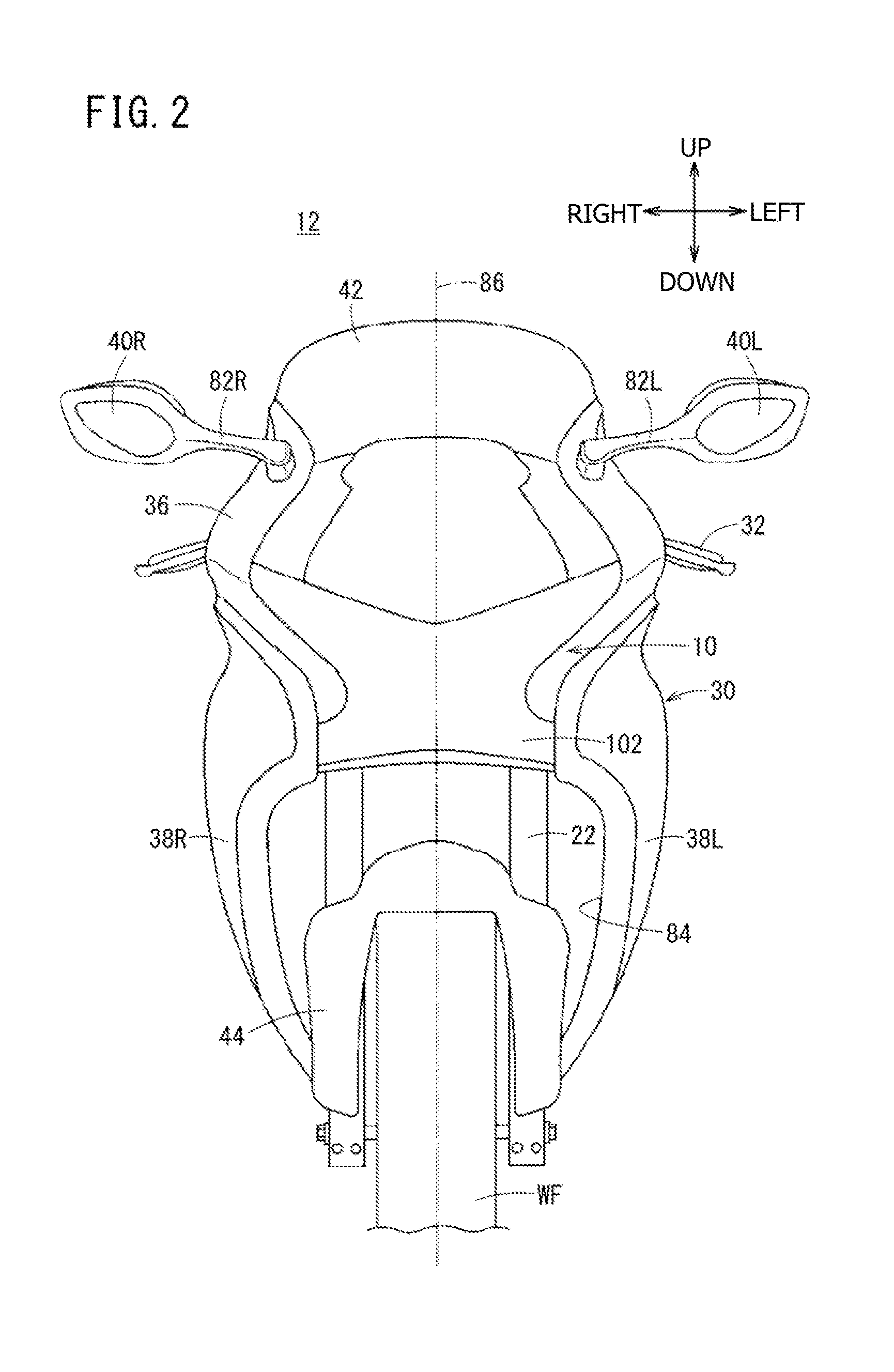
[0028]FIG. 1 is a left side view of a motorcycle (vehicle) 12 having a headlight 10 serving as a vehicle lamp according to the present embodiment (hereinafter also referred to as the headlight 10 according to the present embodiment). FIG. 2 is a front view of the motorcycle 12. It should be noted that, unless otherwise stated, the longitudinal, horizontal, and vertical directions of the motorcycle 12 will be described relative to the direction as seen from the rider seated on a seat 14 of the motorcycle 12. Further, as for the mechanisms or components provided one on the left and another on the right of the vehicle body, letter L is added to the reference symbols of those provided on the left, and letter R is added to the reference symbols of those provided on the right.

[0029]A vehicle body frame 16 mak...


PUM


Abstract

In a headlight of a motorcycle, a holder, first light sources and second light sources are arranged inside a lamp unit. The lamp unit is formed with a housing and an outer lens. The first light sources are main low beam light sources supported by the holder. The second light sources are subordinate low beam light sources that are supported independently by a housing other than the holder, the housing not permitting adjustment of the optical axis, and produce a smaller amount of light than the first light sources.

Description

BACKGROUND OF THE INVENTION[0001]1. Field of the Invention[0002]The present invention relates to a vehicle lamp that has a plurality of light sources and a holder in a lamp unit formed with a housing and a lens arranged therein and adjusts the optical axis of the light sources by tilting the holder.[0003]2. Description of Related Art[0004]Japanese Patent Laid-Open No. 2007-76567 discloses adjusting an optical axis (aiming) by sharing a holder among a plurality of light sources to support the light sources with the single holder. The optical axes of the plurality of light sources are simultaneously adjusted by tilting the single holder.[0005]However, the technology disclosed in Japanese Patent Laid-Open No. 2007-76567 supports a plurality of light sources with a single holder. As a result, there is no flexibility in laying out each light source, making it likely that a vehicle lamp may be restricted in design. Further, all the light sources are supported by the holder. Therefore, in ...

Claims


Application Information

Patent Timeline
IPC IPC(8): F21S8/10B60Q1/06B60Q1/00B62J6/02
CPCF21S48/1104F21S48/13B60Q1/0041B62J6/02B60Q1/06F21S48/1241B60Q1/0683F21S41/19F21S41/143F21S41/28F21S41/321F21S41/50B62J6/024B62J6/026F21S41/148F21S41/33
Inventor OGUCHI, TSUYOSHIKODAIRA, SHIGERUTAKENAKA, NOBUYUKIAOKI, HIDEMASA
Owner HONDA MOTOR CO LTD
Why Eureka
Try Eureka