Image display apparatus and image display method
- Summary
- Abstract
- Description
- Claims
- Application Information
AI Technical Summary
Benefits of technology
Problems solved by technology
Method used
Image

Examples
first embodiment
Overview of Electronic Rearview Mirror According to First Embodiment
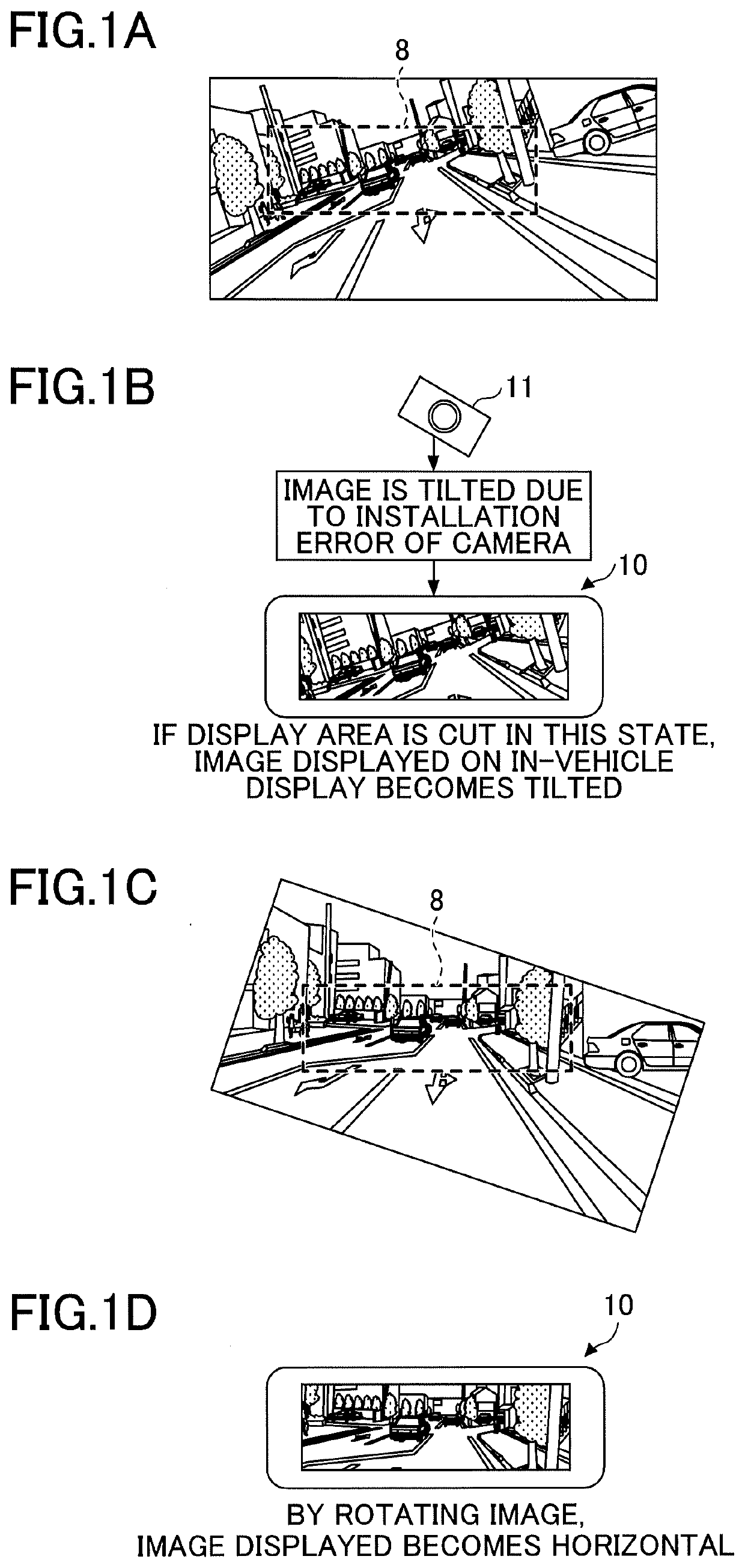
[0034]In a case where a driver corrects an image captured by an imaging device 11 having installation error, an electronic rearview mirror according to a first embodiment performs a “process for moving a CMS area in a vertical direction or in a horizontal direction within the image that has been rotated”. The CMS area is a display area within image data and is displayed on a display.
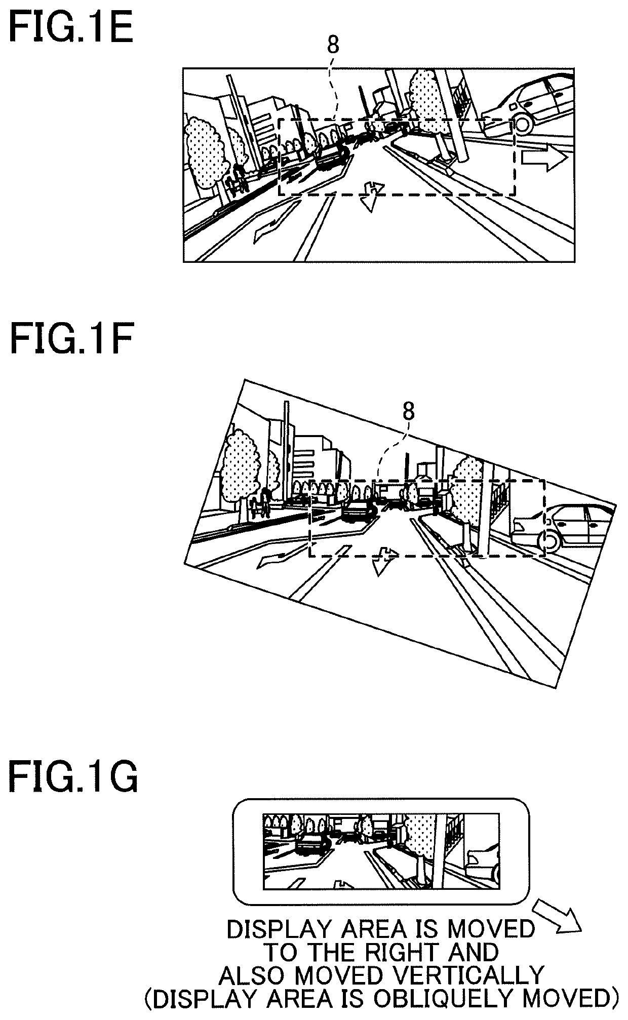
[0035]FIGS. 2A through 2D are drawings illustrating positional adjustment of a CMS area 8 displayed by the electronic rearview mirror of the present embodiment. Similar to FIG. 1C, FIG. 2A illustrates image data that has been rotated. Similar to FIG. 1C, FIG. 2B illustrates a CMS area 8 after the rotation of the image data. In this state, if the driver moves the CMS area 8 up, down, left, or right, the electronic rearview mirror 10 moves the CMS area 8 in the vertical direction or in the horizontal direction within the image data that ha...
second embodiment
[0084]In the first embodiment, an example in which a CMS area 8 is moved vertically or horizontally after the rotation of image data has been described. In a second embodiment, an example in which image data is rotated after the vertical or horizontal movement of a CMS area 8 will be described.
[0085]FIGS. 9A through 9F are drawings illustrating a problem with rotating image data after a CMS area is vertically or horizontally moved. As illustrated in FIG. 9A and FIG. 9B, because the imaging device 11 installed on the rear of the vehicle is rotated clockwise due to installation error, CMS area image data displayed by an electronic rearview mirror 10 is tilted.
[0086]Before rotating the image data, the CMS area 8 has moved vertically or horizontally by a driver. FIG. 9C illustrates an example of image data in which the CMS area 8 has moved to the left. In this state, the CMS area 8 displayed on the display 15 of the electronic rearview mirror 10 is cut out. As illustrated in FIG. 9D, CM...
third embodiment
[0112]In a third embodiment, an electronic rearview mirror 10 that can be employed in both the image processing of the first embodiment and the image processing of the second embodiment will be described.
[0113]A process may be separated in accordance with whether a CMS area 8 is moved after the rotation of image data (first embodiment) or image data is rotated in a state where the center of the image data does not coincide with the center of the CMS area 8 (second embodiment).
[0114]FIG. 13 is a flowchart illustrating an example of a process for selecting a method for displaying CMS area image data.
[0115]First, the operation receiving unit 22 determines whether a rotation operation of image data is received (S210). If it is determined that the rotation operation is not received (no in step S210), the process proceeds to step S250.
[0116]If it is determined that the rotation operation is received (yes in step S210), the image rotating and moving unit 23 rotates the image data (S220). N...
PUM
 Abstract
Description
Claims
Application Information
 - R&D
- Intellectual Property
- Life Sciences
- Materials
- Tech Scout
- Unparalleled Data Quality
- Higher Quality Content
- 60% Fewer Hallucinations
Browse by: Latest US Patents, China's latest patents, Technical Efficacy Thesaurus, Application Domain, Technology Topic, Popular Technical Reports.
© 2025 PatSnap. All rights reserved.Legal|Privacy policy|Modern Slavery Act Transparency Statement|Sitemap|About US| Contact US: help@patsnap.com