Objective lens system

a lens system and objective technology, applied in the field of objective lens systems, can solve the problems of increasing the space required for alignment markers on the substrate, not being available for production of devices, etc., and achieve the effects of fine positioning information, large capture range, and valuable backward compatibility

Active Publication Date: 2018-11-29
ASML HLDG NV
View PDF0 Cites 5 Cited by
  • Summary
  • Abstract
  • Description
  • Claims
  • Application Information

AI Technical Summary

Benefits of technology

The alignment system described in this patent makes use of information from the pupil plane of a marker to determine its position. This information can be obtained by detecting intensity variations at different positions in the pupil plane. The system can detect fine positioning information by measuring the relative phases in the intensity variations as the marker is scanned. It can also capture the marker's position by measuring intensity at two closely spaced positions. The system can compensate for errors caused by asymmetries in the marker by detecting phase variations in dark areas of the pupil plane. The alignment system can be used with various different forms of markers and can provide additional features and more accurate alignment. It can also use new alignment markers with higher spatial frequencies for improved robustness and accuracy of alignment. Additionally, a single frequency short grating can be used to reduce the amount of scribe lane real estate devoted to alignment markers.

Problems solved by technology

However, the need to provide two gratings with different periods increases the amount of space required for the alignment markers on the substrate.
It is desirable to minimize the amount of such “silicon real estate” devoted to alignment marks and therefore not available for production of devices.

Method used


Image

  • Objective lens system
  • Objective lens system
  • Objective lens system

Examples


Embodiment Construction

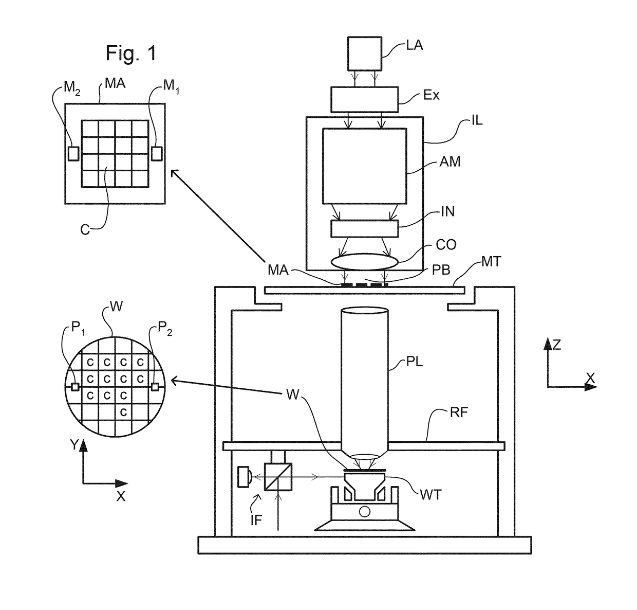
[0061]FIG. 1 schematically depicts a lithographic projection apparatus 1 according to an embodiment of the invention. The apparatus includes a radiation system Ex, IL constructed and arranged to supply a projection beam PB of radiation (e.g. UV or EUV radiation, such as, for example, generated by an excimer laser operating at a wavelength of 248 nm, 193 nm or 157 nm, or by a laser-fired plasma source operating at 13.6 nm). In this embodiment, the radiation system also comprises a radiation source LA. The apparatus also includes a first object (mask) table MT provided with a mask holder constructed and arranged to hold a mask MA (e.g. a reticle), and connected to a first positioning device PM to accurately position the mask with respect to a projection system or lens PL; a second object (substrate) table WT provided with a substrate holder constructed and arranged to hold a substrate W (e.g. a resist-coated silicon wafer), and connected to a second positioning device PW to accurately...


PUM

PropertyMeasurementUnit
wavelengthaaaaaaaaaa

Abstract

An alignment system uses a self-referencing interferometer that incorporates an objective lens system having a plurality of lens element groups. In an embodiment, the objective is configured and arranged to provide a large numerical aperture, long working distance, and low wavefront error.

Description

CROSS-REFERENCE TO RELATED APPLICATIONS[0001]This application claims priority of U.S. Provisional Patent Application No. 62 / 264,155, which was filed on Dec. 7, 2015, and which is incorporated herein in its entirety by reference.BACKGROUND OF THE INVENTIONField of the Invention[0002]The present invention relates to an objective lens system which may find application in a lithographic projection apparatus, a device manufacturing method, and a device manufactured thereby.Description of the Related Art[0003]The term “patterning device” as here employed should be broadly interpreted as referring to device that can be used to endow an incoming radiation beam with a patterned cross-section, corresponding to a pattern that is to be created in a target portion of the substrate. The term “light valve” can also be used in this context. Generally, the pattern will correspond to a particular functional layer in a device being created in the target portion, such as an integrated circuit or other ...

Claims


Application Information

Patent Timeline
Patent Type & Authority Applications(United States)
IPC IPC(8): G02B27/00G02B17/02G03F9/00G03F7/20G01B11/27G01B9/02
CPCG02B27/0025G02B17/026G03F9/7049G03F7/70141G01B11/272G01B9/02058G02B21/02
Inventor SOBOLEV, KIRILL URIEVICH
Owner ASML HLDG NV
Why Eureka
Try Eureka