
Method of Rapidly Melting Metal for 3D Metal Printers by Electromagnetic Induction

Inactive Publication Date: 2018-11-08
ZENG RICHARD +1
View PDF7 Cites 5 Cited by
  • Summary
  • Abstract
  • Description
  • Claims
  • Application Information

AI Technical Summary

Benefits of technology

The patent text describes a new and cost-effective 3D metal printing method that allows for direct heating and rapid melting of metals, resulting in higher energy conversion efficiency, higher deposition rates, smaller oxide, higher safety and controllability, faster printing, and larger-size metal components manufacturing. Overall, this method solves many of the current limitations of existing 3D metal printing methods.

Problems solved by technology

3D printing can create complex parts that traditional methods cannot process.
This residue will obviously form a contaminated product.
In the direct metal printing process, the laser beam welding sintering process is expensive due to the use of laser.
The electron beam sintering process is also expensive (requires a very high vacuum environment), and has very power consumption.
The size and the shape of the object will be limited due to the cavity space.
The plasma arc process provides a relatively high deposition rate, but the molding accuracy is low and the resolution is low because it is difficult to control the metal wire to feed it into the small liquid pool of the made object.
The 3D metal printing is technically more challenging than the 3D printing of other materials due to the high temperature during the metal forming process and the tendency of the metal oxidation to occur as the temperature rises in the air.
In addition, the metal powder per unit mass is more expensive than metal ingots.
The fine particles of the metal powder are also more expensive than the large particles of the metal powder.
In addition, the surface area of the metal powder is larger than that of the metal ingot with same mass, and the metal oxidation on the surface is more serious than that of the metal ingot.
This serious oxidation may cause dangerous combustion.
Compared to the metal ingots with same mass, metal wire is very expensive in metal arc welding process.
Although the metal powder metallurgy process has a very high printing speed, it is very time-consuming because of the need for long time sintering.
In addition, the metal powder is easier to oxidize and more expensive than that of the metal block.
The sintering process is carried out in the fireplace, and thus the printed three-dimensional object is also limited in size.
This sintering process usually takes a long time.
Thus the metal heating efficiency is low, the heating speed is slow, and the crucible temperature is very high.
Therefore, this method is unsafe and will affect the environment.
Obviously, the traditional 3D metal printing methods such as laser beam, electron beam, plasma arc and so on cannot implement fast printing and cannot form large metal parts.
They cannot be popularized because of the high prices.
The electric heater method is inefficient, slow, and the temperature of crucible is very high, all of these affect the environment and are dangerous.

Method used


Image

  • Method of Rapidly Melting Metal for 3D Metal Printers by Electromagnetic Induction
  • Method of Rapidly Melting Metal for 3D Metal Printers by Electromagnetic Induction
  • Method of Rapidly Melting Metal for 3D Metal Printers by Electromagnetic Induction

Examples


Embodiment Construction

[0022]For a better understanding of the invention, an embodiment of the present invention will be described in detail hereinafter in conjunction with the drawings.

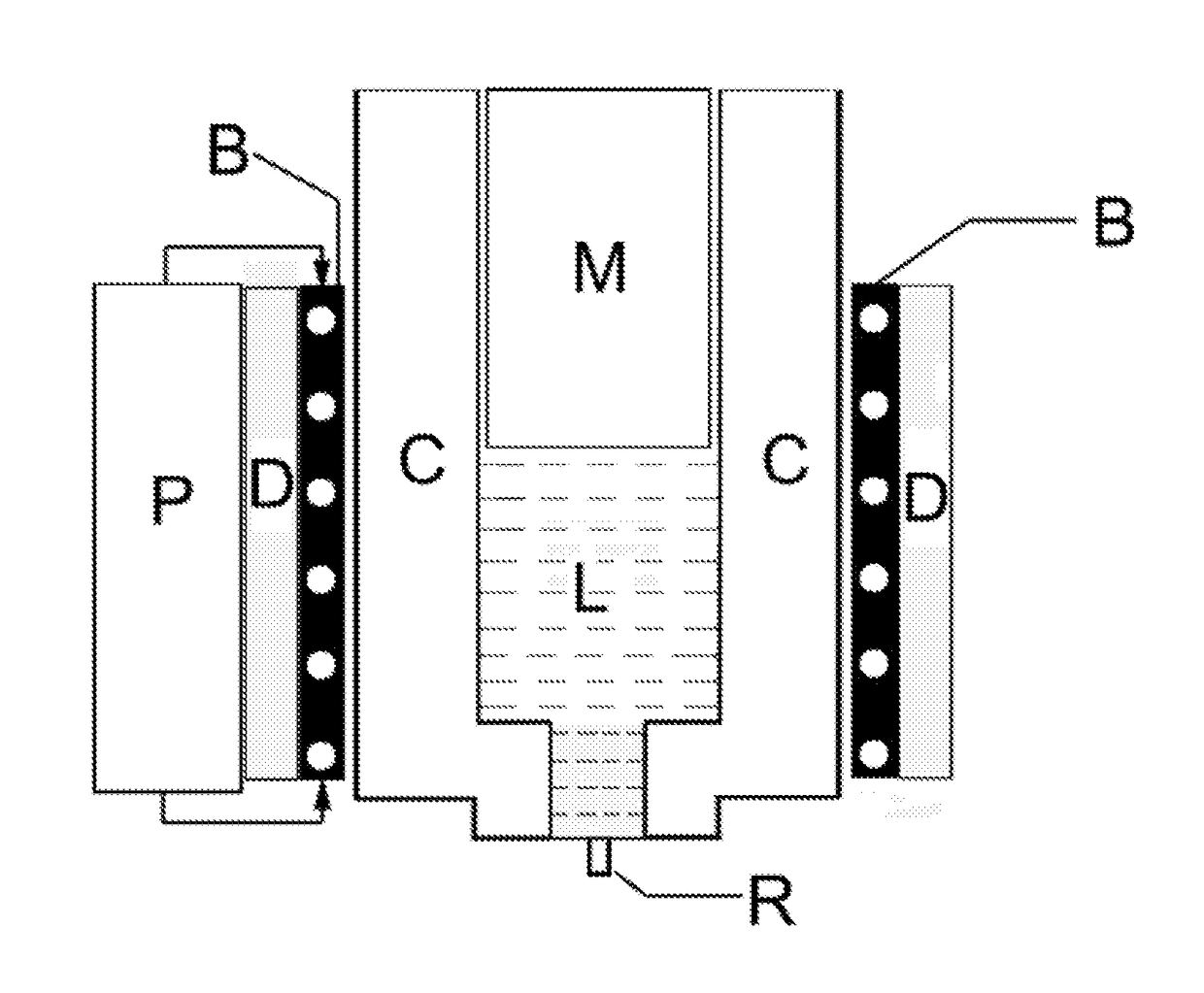
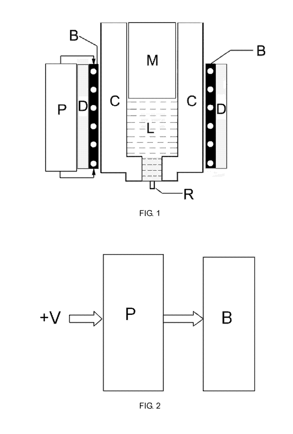
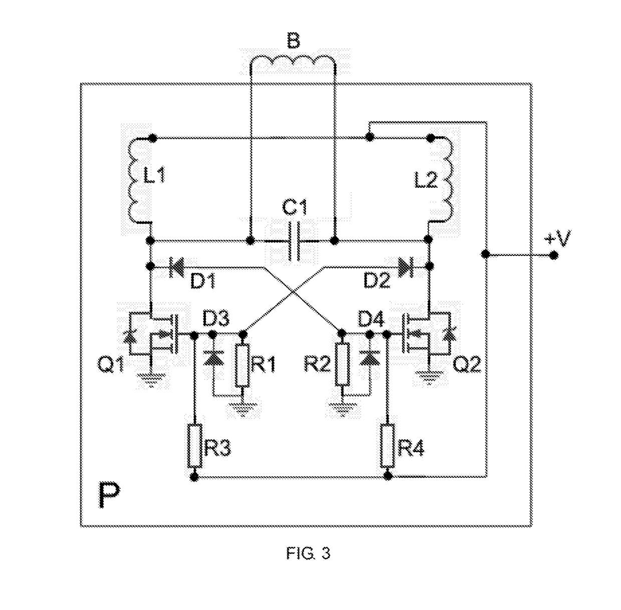
[0023]As shown in FIG. 1, the method of rapidly melting metal for 3D metal printers by electromagnetic induction comprises a nozzle (R), a crucible (C), a middle-high frequency inverter power supply (P), an electromagnetic induction coil (B), a cooling device (D), and metal to be melted (M). The electromagnetic induction coil (B) surrounds the crucible (C), and the cooling device (D) cools the electromagnetic induction coil (B). The middle-high frequency inverter power supply (P) drives the electromagnetic induction coil (B) by high current middle-high frequency (200 Hz to 2 MHz) sine wave or square wave signal, a high density magnetic field line is generated in the electromagnetic induction coil (B) and produces a large eddy current in the metal (M) in the crucible (C), so the metal (M) in the crucible (C) is rapidly melt...


PUM


Abstract

This invention relates to the field of 3D metal printing, and more particularly to a method of rapidly melting metal for 3D metal printers by electromagnetic induction. This is a new cost-effective 3D metal printing method that enables direct heating and rapid melting of metals, higher energy conversion efficiency, higher deposition rates, smaller oxide, higher safety and controllability, faster printing, and larger-size metal components manufacturing.

Description

CROSS-REFERENCE TO RELATED APPLICATIONS[0001]Not Applicable.FIELD OF THE INVENTION[0002]The present invention relates to the field of 3D metal printing, and more particularly to a method of rapidly melting metal for 3D metal printers by electromagnetic induction.BACKGROUND OF THE INVENTION[0003]As metal is used for making many parts and components, metal parts with complex shapes are widely used in aerospace, shipbuilding, automotive, machine, electronics, and pharmaceutical fields. 3D printing can create complex parts that traditional methods cannot process. The use of 3D metal printing technology can greatly reduce the demand for spare parts, saving storage and related facilities and input costs. Large metal components include aircraft fuselage, aircraft engines, aviation equipment, railway cars, rails, hulls, ocean-going masts, trucks, cars, nuclear reactor control rods, oil casing, electro-hydraulic turbines, etc. Small metal components include automotive engines, gears, bicycle...

Claims


Application Information

Patent Timeline
IPC IPC(8): H05B6/10B33Y10/00B33Y30/00B33Y40/00B33Y50/02H05B6/06H05B6/34H05B6/42H05B6/36
CPCH05B6/101B33Y10/00B33Y30/00B33Y40/00H05B6/367H05B6/067H05B6/34H05B6/42B33Y50/02
Inventor ZENG, RICHARDZENG, GUANG XING
Owner ZENG RICHARD
Learn More