Gas redirecting device for liquid-gas contacting column

Active Publication Date: 2018-11-08
TOTAL PUTEAUX FR +2
View PDF0 Cites 2 Cited by
  • Summary
  • Abstract
  • Description
  • Claims
  • Application Information

AI Technical Summary

Benefits of technology

This patent describes a gas-directing system for a liquid-gas contacting column. The system includes several gas-rewiring tubes that redirect the flow of gas from one zone to another. The technical effect of this invention is that it allows for more efficient gas flow and better contact between gas and liquid in the column. The patent also describes the dimensions and configurations of the gas-Redirecting tubes.

Problems solved by technology

FLNG technology also provides a number of economic advantages, for example, pumping gas to the shore can be prohibitively expensive due to the construction of pipelines.
However, the current FLNG technology challenge is that each element of the natural-gas processing plant and liquefaction unit needs to fit into a floating support having limited space, while maintaining appropriate levels of safety and achieving the desired specification.
In an underloaded area, the gas is not effectively treated, while in an overloaded area, the gas is over-treated.
It results in an inhomogeneity of the gas treatment and a global loss of efficiency of the liquid-gas contacting column.
This may significantly impact the column design basis (increased diameter and height of the column are needed to compensate the loss of efficiency) and consequently the whole FLNG project.
Industrial feedback on floating support is limited and does not allow precise predictions on this global loss of gas treatment efficiency of the liquid-gas contacting column.
However, this would increase constraints exerting onto the structure of the floating support itself.
This means that the size of the floating support would be so large, that economic feasibility of the project can be jeopardized.

Method used


Image

  • Gas redirecting device for liquid-gas contacting column
  • Gas redirecting device for liquid-gas contacting column
  • Gas redirecting device for liquid-gas contacting column

Examples


example 1

[0146]Gas-Redirecting Device with m=8

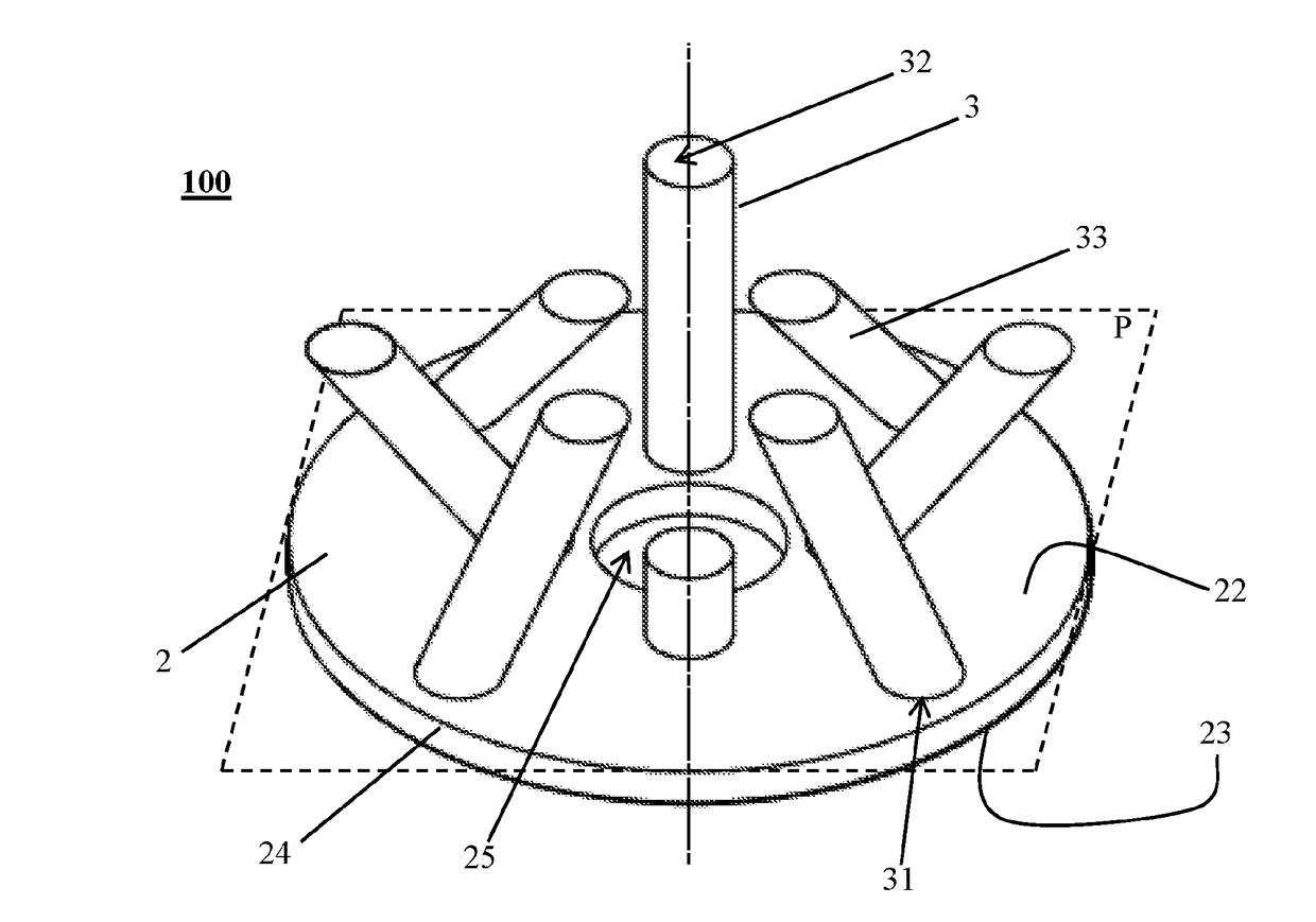
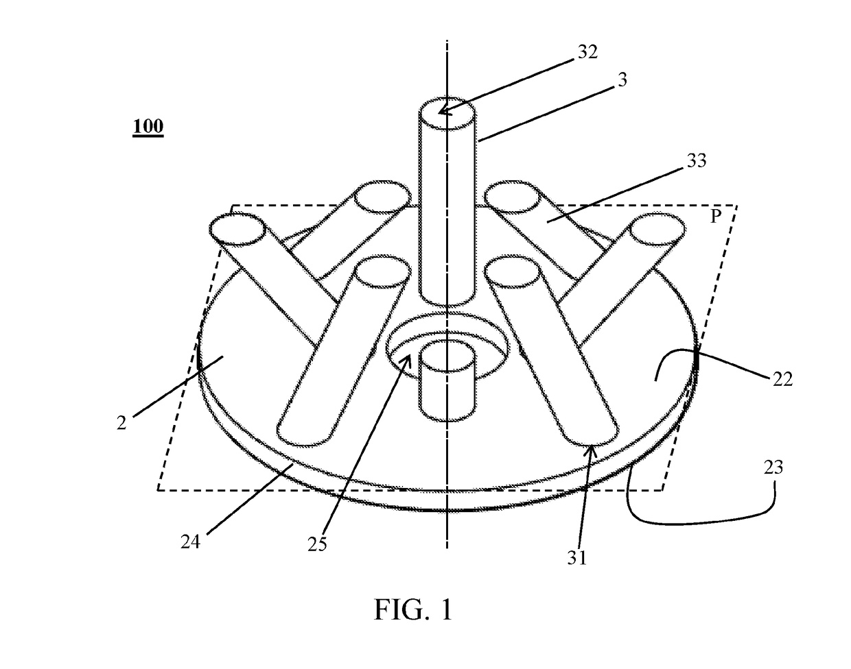
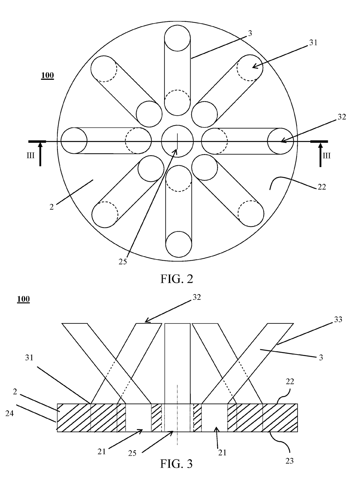
[0147]As illustrated by FIGS. 1 to 4, the gas-redirecting device 100 comprises eight straight gas-redirecting tubes 3, a circular plane plate 2 having eight circular through-holes 21 and a circular central orifice 25. Four of the through-holes 21 are homogenously disposed on a first circle C1 which is coaxial with the circular central orifice 25. The four other through-holes are homogeneously disposed on a second circle C2 which is coaxial with the circular central orifice and which presents a radius greater than the radius of the first circle C1. The through-holes 21 on the first circle C1 angularly alternate with the through-holes on the second circle C2. Each though-hole 21 is fluidly connected to one gas-redirecting tube 3 by the inlet end 31 thereof.

[0148]The gas-redirecting tubes 3 are inclined so that:[0149]the outlet end 31 and the inlet end 32 of each tube are radially aligned;[0150]the orthogonal projection 321 on the upper plane of the...

example 2

[0152]Gas-Redirecting Device, wherein m=3

[0153]As illustrated by FIGS. 7 to 9, the gas-redirecting device 100 comprises three straight gas-redirecting tubes 3, a circular plane plate 2 having three circular through-holes 21 and a circular central orifice 25. Each though-hole 21 is fluidly connected to one gas-redirecting tube 3 by the inlet end 31 of the one gas-redirecting tube 3.

[0154]The gas-redirecting tubes 3 are inclined so that:[0155]the orthogonal projection 321 on the upper plane of the circular plane plate 2 (which is the upper surface of the circular plane plate) of all outlet ends 32 and all inlet ends 31 of the gas-redirecting tubes are disposed on a same circle C3 coaxial to the circular central orifice 25;[0156]the orthogonal projection 321 of the outlet ends 32 alternate with the inlet ends 31.

[0157]Thus, the gas-redirecting device 100 presents a 3-fold rotational symmetry and the three gas-redirecting tubes 3 of the gas-redirecting device 100 can redirect the gas fl...


PUM


Abstract

The present invention relates to a gas-redirecting device presenting an upper plane and a plurality of gas-redirecting tubes comprising an inlet end and an outlet end. For each gas-redirecting tube, the orthogonal projections of the inlet end and the outlet end onto the upper plane have an over-lapping area of at most 50% of the total area of the upper plane covered by the orthogonal projections. Also provided is a liquid-gas contacting column comprising a gas-redirecting device, a floating support comprising a liquid-gas contacting column, at least two packed beds and a method for improving the efficiency of a liquid-gas contacting column which is based on redirecting the gas from a wetted zone of a lower packed bed to a wetted zone of the higher packed bed.

Description

RELATED APPLICATIONS[0001]The present application is a National Phase entry of PCT Application No. PCT / IB2015 / 002178, filed Oct. 30, 2015, said application being hereby incorporated by reference herein in its entirety.FIELD OF THE INVENTION[0002]The present invention relates to the improvement of gas processing efficiency in an oscillating liquid-gas contacting column placed on a floating support.BACKGROUND OF THE INVENTION[0003]Raw natural gas, coming primarily from crude oil wells, gas wells and condensate wells, comprises varying amounts of contaminants such as acid gases (carbon dioxide (CO2), hydrogen sulfide (H2S), and mercaptans such as methanthiol), water and mercury. To be marketed, raw natural gas must be purified in natural-gas-processing plants to meet the quality standards specified by the distribution companies or the LNG specifications. A natural-gas processing plant comprises different process units to remove impurities such as several liquid-gas contacting columns t...

Claims


Application Information

Patent Timeline
IPC IPC(8): B01D53/14B01D3/20B01D53/18B01D3/24B01D3/32
CPCB01D3/20B01D53/1406B01D53/1462B01D53/18B01D2259/4566B01J2208/00849B01D1/0005B01D3/24B01D3/324B01D53/185
Inventor WEISS, CLAIREMAUBERT, THOMASFOURNIE, MAXIMEFOURATI, MANELBEARD, PHILIPPEALIX, PASCALPERDU, GAUTHIERSALAIS, CLEMENTCARLIER, VINCENT
Owner TOTAL PUTEAUX FR
Why Eureka
Try Eureka