
Wavelength Division Multiplexing/Demultiplexing Optical Transceiving Assembly Based on Diffraction Grating

a diffraction grating and optical transceiving technology, applied in multiplex communication, instruments, optical elements, etc., can solve the problems of high coupling difficulty, large insertion loss, high cost, etc., and achieve the effect of reducing coupling loss and insertion loss, simple assembly process, and better diffraction grating filtering property

Active Publication Date: 2018-11-01
WUHAN TELECOMM DEVICES
View PDF0 Cites 9 Cited by
  • Summary
  • Abstract
  • Description
  • Claims
  • Application Information

AI Technical Summary

Benefits of technology

The present invention has several benefits: better diffraction grating filtering, smaller coupling and insertion loss with wavelength, larger optical element sizes, and a simpler assembly process. It is better suited for manufacturing multi-channel optical transceiving assemblies and reduces the size and cost of the module. The transmitting and receiving elements share a common filter optical element and most of the optical lens, reducing the number of small components. These technical effects make it easier to build and operate high-speed optical transceiving modules.

Problems solved by technology

However, it has high cost, high difficulty in coupling, and big insertion loss, so it is not conducive to meet the requirements on optical transceiving modules for low power consumption.

Method used


Image

  • Wavelength Division Multiplexing/Demultiplexing Optical Transceiving Assembly Based on Diffraction Grating
  • Wavelength Division Multiplexing/Demultiplexing Optical Transceiving Assembly Based on Diffraction Grating
  • Wavelength Division Multiplexing/Demultiplexing Optical Transceiving Assembly Based on Diffraction Grating

Examples


Embodiment Construction

[0019]In the following, the present invention will be described in further detail with reference to the drawings and the detailed embodiments. Examples of the embodiments are shown in the drawings, wherein the same or similar labels represent the same or similar elements or components having the same or similar functions from beginning to end. The following embodiments illustrated with reference to the drawings are exemplary, only used to explain the technical solutions of the present invention, and should not be understood as a limitation to the present invention.

[0020]In the description of the present invention, the orientation or position relations indicated by the terms “inside”, “outside”, “longitudinal”, “lateral”, “upper”, “lower”, “top” and “bottom” are the orientations or positions based on the drawings, are only used to facilitate the describing of the present invention, rather than requiring the present invention to be manufactured or operated in the specific orientations...


PUM


Abstract

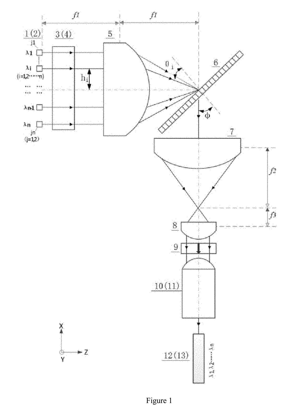
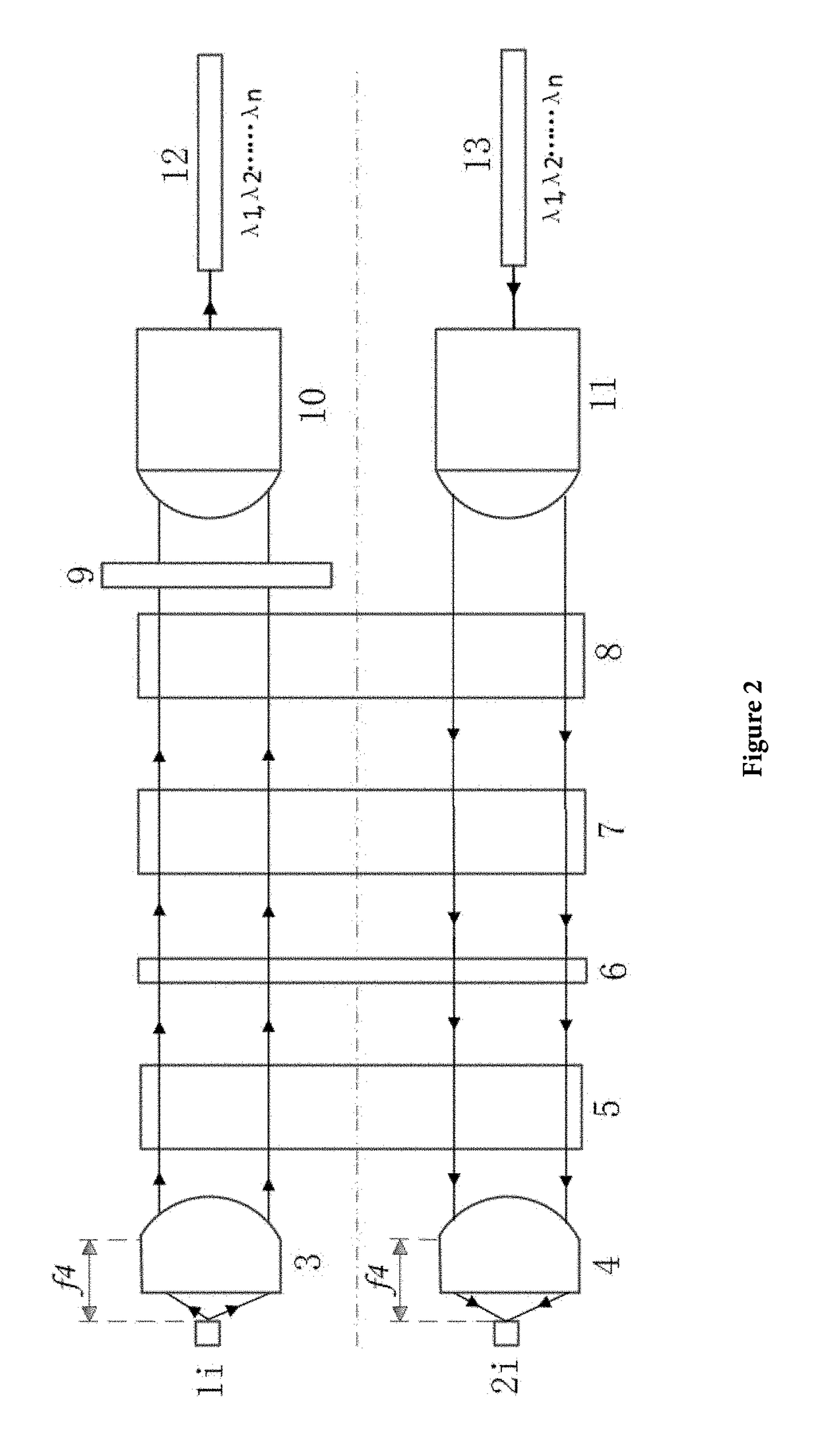
The present invention provides a wavelength division multiplexing / demultiplexing optical transceiving assembly based on a diffraction grating, which is an uplink optical emitting unit and a downlink optical receiving unit that comprise a laser chip array, a light receiving detector array, a first fast axis collimating lens, a second fast axis collimating lens, a first slow axis collimating lens, a diffraction grating, a slow axis focusing lens, a second slow axis collimating lens, an optical isolator, a coupling output lens, a coupling input lens, a coupling outputting optical fiber and a coupling inputting optical fiber. The wavelength division multiplexing / demultiplexing optical transceiving assembly solves the technical problem of sharing a diffraction grating to realize a wavelength division multiplexing / demultiplexing function, achieves the beneficial effects of better diffraction grating filtering property, smaller light path coupling loss and insertion loss correlative with wavelength, larger independent optical element sizes, and simpler assembly process, and is more suitable for manufacturing a multi-channel wavelength division multiplexing / demultiplexing optical transceiving assembly.

Description

TECHNICAL FIELD[0001]The present invention relates to the technical field of optical communication, and particularly, to a wavelength division multiplexing / demultiplexing optical transceiving assembly based on a diffraction grating.BACKGROUND ART[0002]With the universal popularization of the network information industry and the outcoming explosive growth of global data and the rise of the big data industry, data centers have become a new market opportunity of the optical communication industry, and high bandwidth optical interconnection has gradually replaced electrical interconnection, and will develop towards the trend of high speed and large capacity. Multi-channel optical modules adopt multiplex optical emitting and receiving techniques, and have the characteristics of large communication capacity, low energy consumption and miniaturization, which has been favored by the industry. Their transmission rate and transmission capacity are much more superior than single-channel transc...

Claims


Application Information

Patent Timeline
IPC IPC(8): G02B6/293H04J14/02
CPCG02B6/2931G02B6/29313H04J14/02G02B6/29304G02B6/4206G02B6/4286G02B6/4296H04B10/2513H04B10/506H04B10/615H04B10/40H04J14/0256G02B6/4215G02B6/29311G02B6/2938
Inventor TANG, XUESHENGZHANG, DIHU, SHENGLEIFU, YONGANFU, YANFENGLIU, CHENGGANGLI, SHIYUSUN, LIPINGMA, WEIDONG
Owner WUHAN TELECOMM DEVICES
Learn More