
Evaluation method for clay and manufacturing method of extrusion molded body

a technology of extrusion molding and extrusion molding, which is applied in the direction of auxillary shaping apparatus, machine/engine, resonance analysis of materials, etc., can solve the problems of preventing stable supply of clay to be used for producing honeycomb structural bodies, various limitations in actual use, and difficulty for screw extruder machines to change the mixing period time, etc., to improve the yield rate of honeycomb structural bodies, suppress defects from being generated, and uniform properties of extrusion molding bodies

Active Publication Date: 2018-10-25
DENSO CORP
View PDF0 Cites 5 Cited by
  • Summary
  • Abstract
  • Description
  • Claims
  • Application Information

AI Technical Summary

Benefits of technology

The patent text describes an evaluation method and a manufacturing method for clay molded bodies, such as ceramic green bodies used in honeycomb structural bodies. The evaluation method uses magnetic resonance imaging (MRI) to detect defects in the clay due to its components, mixing condition, and compression state. The manufacturing method takes into account these defects and adjusts the mixing and compression conditions to produce molded bodies with uniform properties and reduced defects. This results in higher yields of defect-free honeycomb structures.

Problems solved by technology

However, in general, because the properties of the produced clay are evaluated in general by persons highly skilled in the art, this prevents stable supply of clay to be used for producing honeycomb structural bodies.
However, the conventional evaluation method and manufacturing method previously described cannot adequately suppress generation of defects from the produced honeycomb structure body and causes various limitations in actual use.
It is difficult for such screw extruder machines to change the mixing period of time, in which the constituent components of the clay, i.e. ceramic raw material, binder, lubricant, water, etc. are mixed together.
The thinner the cell walls in the ceramic green body extruded by the screw extruder machine is, the more defects are generated in the ceramic green body.
However, such visual inspection cannot quantitatively detect generation of cell-wall deformation such as waved cell walls in ceramic green bodies.
When cell-wall deformations such as waved cell walls are formed in extruded bodies and the honeycomb structural body obtained from the extruded bodies, it is difficult for the cell walls to correctly and adequately support catalyst.
However, the screw extruder machine often generates defects in extruded ceramic green bodies made of clay.
Such defects are derived from the rotary motion of the screw due to the screw structure of the screw extruder machine.
That is, it has been clear that such defects are generated due to the presence of a liquid component oozing from the clay on a screw surface of the screw extruder machine.
When the screw extruder machine performs inadequate extrusion and inadequate compression of the clay, a liquid component such as water is separated from the clay.

Method used


Image

  • Evaluation method for clay and manufacturing method of extrusion molded body
  • Evaluation method for clay and manufacturing method of extrusion molded body
  • Evaluation method for clay and manufacturing method of extrusion molded body

Examples


first exemplary embodiment

[0052]A description will be given of an evaluation method according to a first exemplary embodiment, which performs an evaluation process of evaluating a clay with reference to FIG. 1 to FIG. 5.

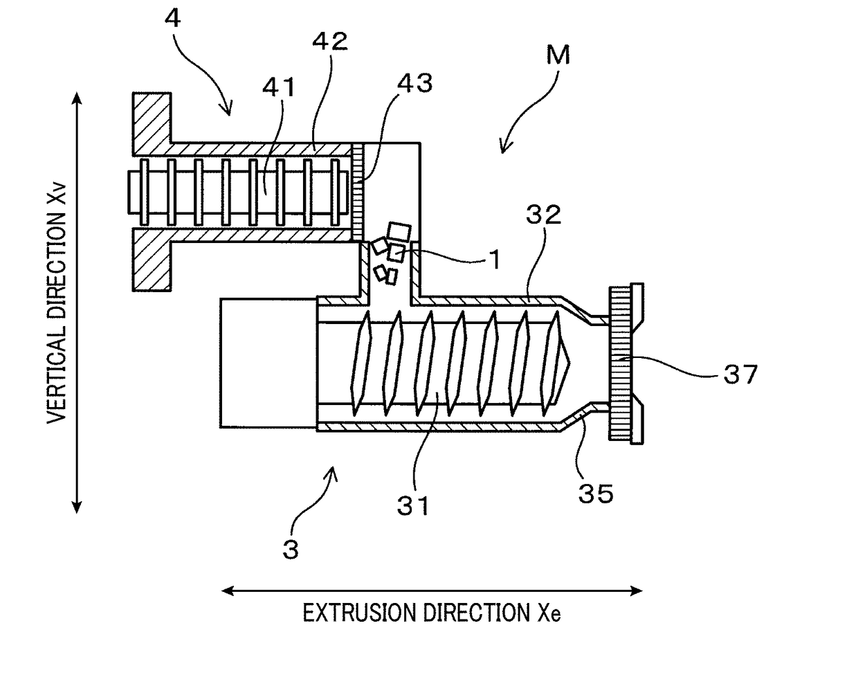
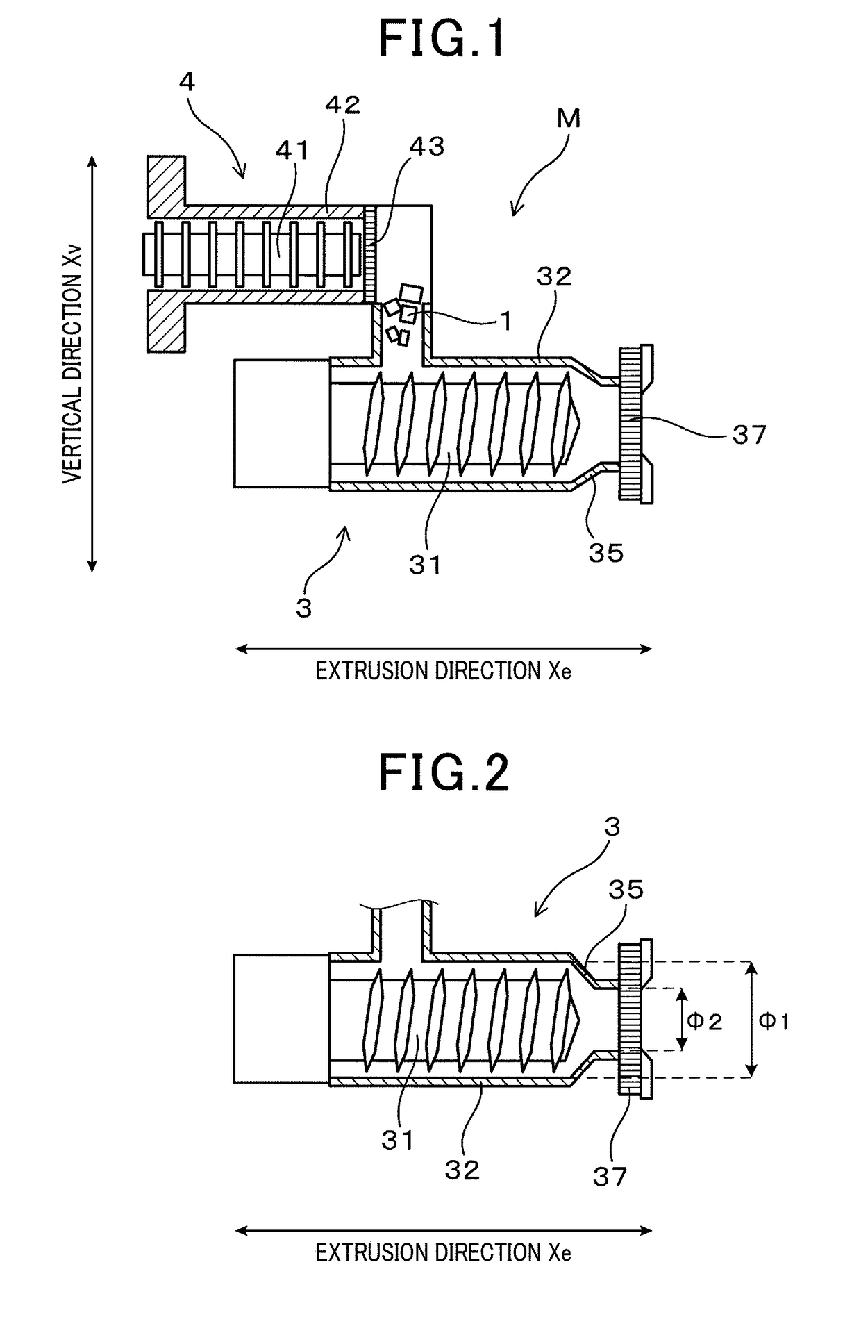
[0053]FIG. 1 is a view showing a schematic cross section of a mixing and screw extruder machine M composed of a screw extruder machine 3 and a mixing machine 4. FIG. 2 is a view showing a schematic cross section of the screw extruder machine 3 in the mixing and screw extruder machine M shown in FIG. 1. The mixing and screw extruder machine M produces a clay.

[0054]The evaluation method according to the first exemplary embodiment performs the evaluation process of evaluating various types of clay produced by the mixing and extrusion molding machine M. The clay is used for producing a honeycomb structural body.

[0055]A description will now be given of the evaluation method with reference to FIG. 1 to FIG. 5.

[0056]The clay is produced by the following processes. In a mixing process, the mixing mac...

second exemplary embodiment

[0101]A description will be given of the manufacturing method according to a secondary exemplary embodiment with reference to FIG. 6 to FIG. 13. The manufacturing method according to the secondary exemplary embodiment manufactures extruded bodies and honeycomb structural bodies. The same components used in the second exemplary embodiment and the first exemplary embodiment will be referred with the same reference numbers and characters.

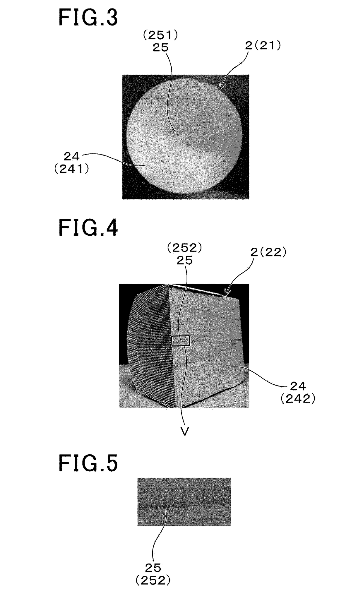
[0102]FIG. 6 is a perspective view showing a structure of a honeycomb structural body H produced by the manufacturing method according to the second exemplary embodiment. That is, the honeycomb structural body H shown in FIG. 6 basically corresponds to the cut product shown in FIG. 4. As shown in FIG. 6, the honeycomb structural body H has an outer skin part H11, a plurality of cell walls H12 having a porous structure, and a plurality of cells C which are formed along the axial direction X of the honeycomb structural body H. The outer skin part H11 has...


PUM

PropertyMeasurementUnit
light transmittanceaaaaaaaaaa
pulse Nuclear Magnetic Resonanceaaaaaaaaaa
T1 relaxation timeaaaaaaaaaa

Abstract

A method performs evaluation of properties of a clay rod, with which a honeycomb structural body is produced. The method mixes raw materials to produce a clay, and extrudes the clay and compresses the extruded clay to produce a clay rod. The method performs NMR to detect at least one of a T1 relaxation time and a T2 relaxation time in each of a normal part and an abnormality part extracted from the clay rod. Each of the T1 relaxation time and the T2 relaxation time corresponds to a relaxation time of nuclear spins of water protons magnetically excited in each of the normal part and the abnormality part. The method performs the evaluation of uniformity of a mixed state and a compression state of the clay rod based on a difference in T1 relaxation time and T2 relaxation time between the normal part and the abnormality part.

Description

CROSS-REFERENCE TO RELATED APPLICATION[0001]This application is related to and claims priority from Japanese Patent Application No. 2017-82908 filed on Apr. 19, 2017, the contents of which are hereby incorporated by reference.BACKGROUND OF THE INVENTION1. Field of the Invention[0002]The present invention relates to evaluation methods performing evaluation of properties of clay and relates to manufacturing methods producing extrusion molded bodies to be used for manufacturing honeycomb structural bodies.2. Description of the Related Art[0003]There has been widely known and used a honeycomb structural body made of ceramics capable of purifying exhaust gas emitted from an internal combustion engine of a motor vehicle, etc. In general, a honeycomb structural body has cell walls and cells. The cell walls are arranged in a honeycomb structure on a cross section, which is perpendicular to an axial direction of, i.e. a longitudinal direction of the honeycomb structural body. Each of the cel...

Claims


Application Information

Patent Timeline
Patent Type & Authority Applications(United States)
IPC IPC(8): B28C5/42B28C1/16B28C1/22F01N3/035C04B38/00F01N3/022G01N33/38
CPCB28C5/4258B28C1/16B28C5/4286B28C1/227F01N3/035C04B38/0009F01N3/0222G01N33/383C04B2111/0081C04B2111/40G01N2011/0053B01D2279/30B01D2046/2496G01N24/081B28B17/0072F01N2330/04C04B35/195C04B38/0006C04B2235/60C04B2235/6021C04B2235/61Y02T10/12C04B35/16C04B35/478C04B35/565B01D46/2498
Inventor HAYASHI, NAOHIRO
Owner DENSO CORP
Learn More