Fuel-cell power generation unit and fuel-cell stack

Active Publication Date: 2018-10-11
MORIMURA SOFC TECH CO LTD
View PDF0 Cites 3 Cited by
  • Summary
  • Abstract
  • Description
  • Claims
  • Application Information

AI Technical Summary

Benefits of technology

The present patent describes a fuel cell electricity generation unit that includes a single cell with an electrolyte layer, and two metal interconnectors with a metal separator in between. The unit also has a gas sealing member that separates the anode and cathode chambers. The gas sealing member has a contact overlap region with the interconnectors, and weld portions are formed at a position that is further out than the contact overlap region. This prevents the gas sealing member from being affected by protrusions on the weld portions and ensures effective sealing without creating a gas bypass. The gas sealing member also has a second contact portion that seals between the separator and interconnector, and a space is formed between the gas sealing member and the interconnectors to accommodate a sealing material. Overall, this design improves the gas sealing efficiency and assembly accuracy of the fuel cell electricity generation unit.

Problems solved by technology

In such a structure, the surface flatness of the separator may fail to be maintained due to the presence of a protrusion (e.g., bead) formed on the weld portion, and the gas sealing member may be prevented from being in good contact with the surface of the separator, resulting in impairment of gas sealing of the cathode chamber by the gas sealing member.

Method used


Image

  • Fuel-cell power generation unit and fuel-cell stack
  • Fuel-cell power generation unit and fuel-cell stack
  • Fuel-cell power generation unit and fuel-cell stack

Examples


first embodiment

[0038]A.

[0039]A-1. Structure of fuel cell stack 100:

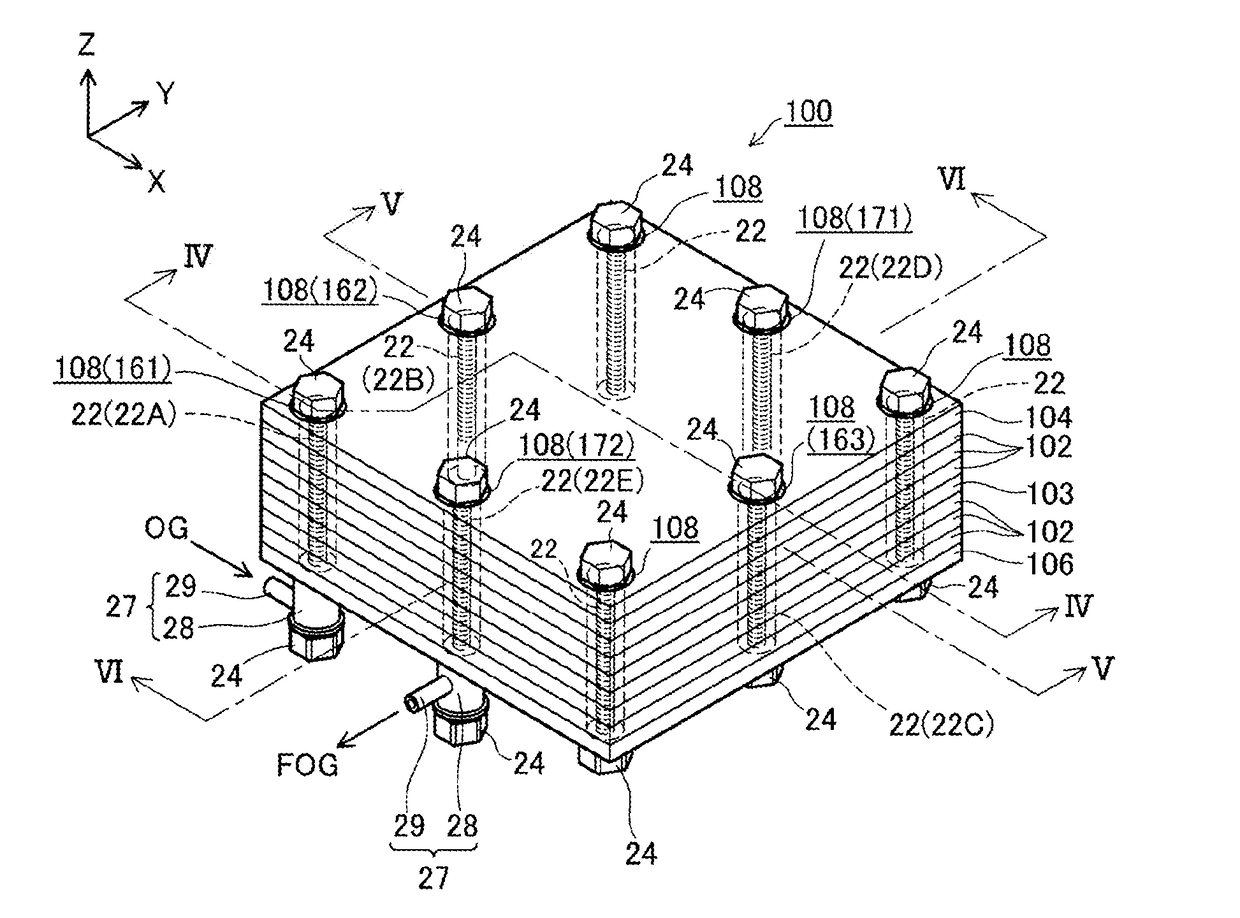
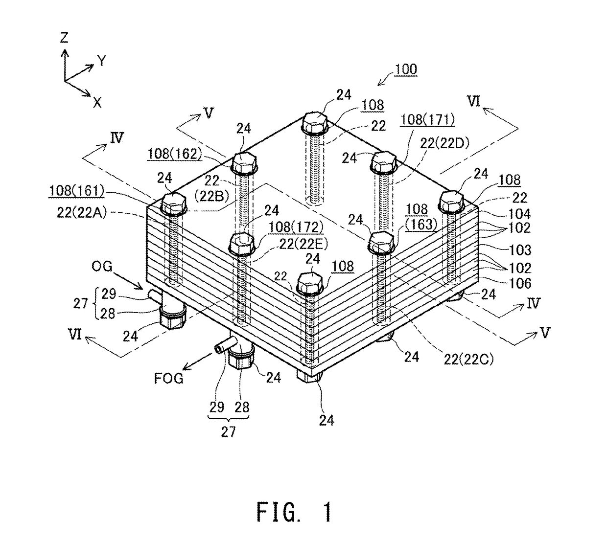
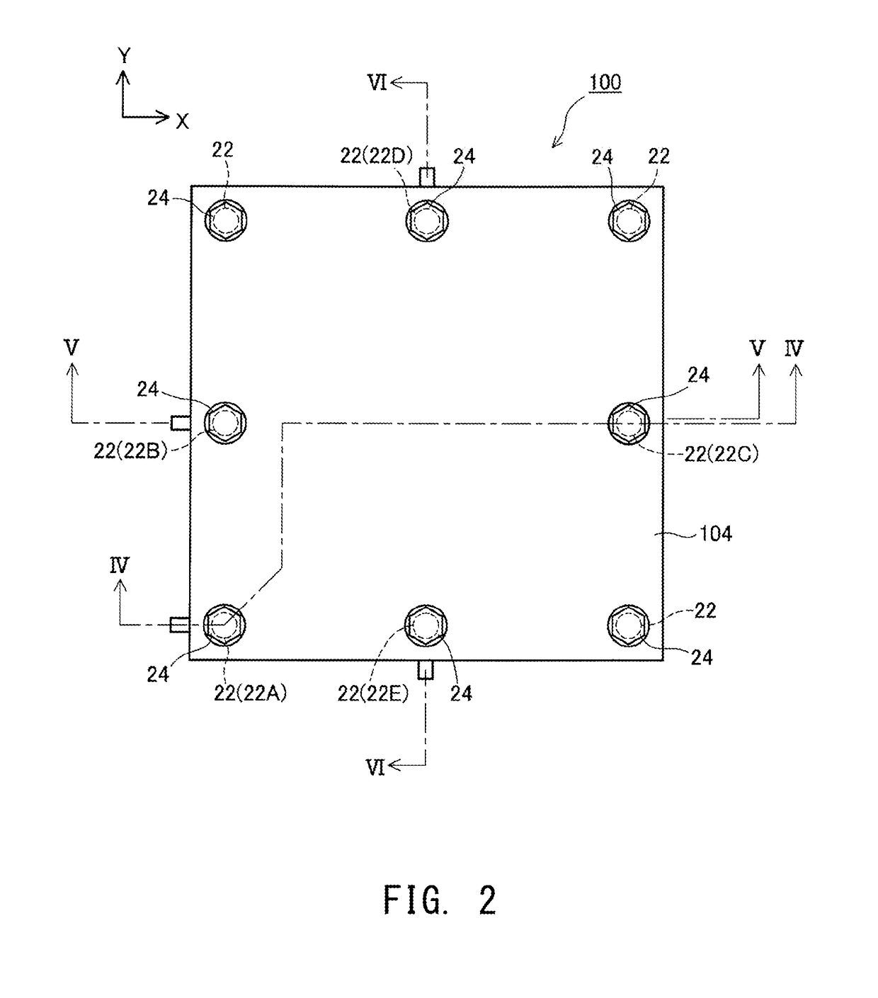
[0040]FIGS. 1 to 6 are explanatory views schematically illustrating the structure of a fuel cell stack 100 according to a first embodiment. FIG. 1 illustrates the external appearance of the fuel cell stack 100; FIG. 2 is a top plan view of the fuel cell stack 100; FIG. 3 is a bottom plan view of the fuel cell stack 100; FIG. 4 is a sectional view of the fuel cell stack 100 taken along line IV-IV of FIGS. 1 to 3; FIG. 5 is a sectional view of the fuel cell stack 100 taken along line V-V of FIGS. 1 to 3; and FIG. 6 is a sectional view of the fuel cell stack 100 taken along line VI-VI of FIGS. 1 to 3. FIGS. 1 to 6 show mutually orthogonal X-axis, Y-axis, and Z-axis for specifying orientation. In the present specification, for the sake of convenience, the positive Z-axis direction is called the upward direction, and the negative Z-axis direction is called the downward direction; however, in actuality, the fuel cell stack 100 may be dis...

second embodiment

[0080]B.

[0081]FIG. 15 is an explanatory view illustrating the specific structure of an electricity generation unit 102a according to a second embodiment. The electricity generation unit 102a of the second embodiment differs from the electricity generation unit 102 of the first embodiment shown in FIG. 12 in terms of the structure of a cathode-side frame 130a. The other components of the electricity generation unit 102a of the second embodiment, which are the same as those in the first embodiment, are denoted by the same reference numerals, and description thereof is omitted.

[0082]As described above, in the electricity generation unit 102 of the first embodiment shown in FIG. 12, the cathode-side frame 130 is formed so as not to overlap with the first and second weld portions 410 and 420 in the Z-axis direction. In contrast, in the electricity generation unit 102a of the second embodiment shown in FIG. 15, the cathode-side frame 130a overlaps with the first and second weld portions 4...

third embodiment

[0085]C.

[0086]FIG. 16 is an explanatory view illustrating the specific structure of an electricity generation unit 102b according to a third embodiment. The electricity generation unit 102b of the third embodiment differs from the electricity generation unit 102 of the first embodiment shown in FIG. 12 in terms of the structures of an interconnector 150b and a cathode-side frame 130b. The other components of the electricity generation unit 102b of the third embodiment, which are the same as those in the first embodiment, are denoted by the same reference numerals, and description thereof is omitted.

[0087]In the electricity generation unit 102b of the third embodiment, the interconnector 150b has a thin plate portion 152 overlapping with the first and second weld portions 410 and 420 in the Z-axis direction. The thin plate portion 152 is formed through grooving of the interconnector 150b from its surface facing the cathode-side frame 130b such that the interconnector 150b is thinned ...


PUM


Abstract

A fuel cell electricity generation unit including a single cell; first and second interconnectors; a separator; a metal frame member disposed between the separator and the first interconnector; and a gas sealing member having a contact portion in contact with the surfaces of the separator and the second interconnector. The unit has a contact overlap region overlapping with the contact portion in a first direction, and each of the gas sealing member, the separator, the frame member, the first interconnector, and the second interconnector is present in the contact overlap region. At least one of a first weld portion sealing between the separator and the frame member and a second weld portion sealing between the frame member and the first interconnector is formed at a position whose distance from the periphery of the single cell is greater than the distance between the periphery and the contact overlap region.

Description

TECHNICAL FIELD[0001]A technique disclosed in the present specification relates to a fuel cell electricity generation unit and a fuel cell stack.BACKGROUND ART[0002]A known type of a fuel cell is a solid oxide fuel cell (hereinafter may be referred to as “SOFC”). A fuel cell electricity generation unit (hereinafter may be referred to simply as an “electricity generation unit”), which is the smallest unit of electricity generation of an SOFC, includes a single cell, a metal separator, first and second interconnectors, a metal frame member, and a gas sealing member. The single cell includes an electrolyte layer, a cathode, and an anode such that the cathode and the anode face each other in a predetermined direction (hereinafter referred to as “first direction”) and the electrolyte layer intervenes between these electrodes. The separator is a frame member having a through hole, and a portion of the separator surrounding the through hole is bonded to a peripheral portion of the single c...

Claims


Application Information

Patent Timeline
IPC IPC(8): H01M8/0286H01M8/1007H01M8/0206H01M8/0247H01M8/0273
CPCH01M8/0286H01M8/1007H01M8/0206H01M8/0247H01M8/0273H01M8/242H01M2008/1293Y02E60/50H01M8/0271
Inventor MORIKAWA, TETSUYA
Owner MORIMURA SOFC TECH CO LTD
Why Eureka
Try Eureka