
Pressure sensing ventricular assist devices and methods of use

a technology of ventricular assist and pressure sensing, which is applied in the field of pressure sensing ventricular assist devices and methods of use, can solve the problems that pump flow rate information alone may be of limited value, and achieve the effect of increasing the accuracy of flow rate estimation

Active Publication Date: 2018-10-04
TC1 LLC
View PDF2 Cites 16 Cited by
  • Summary
  • Abstract
  • Description
  • Claims
  • Application Information

AI Technical Summary

Benefits of technology

The patent text discusses the importance of measuring cardiovascular pressure to gather valuable data that can help determine a patient's hemodynamic state and optimize blood pump settings. This is particularly useful for LVAD applications. The text explains that real-time pressure measurements can provide information about various clinical parameters, such as arterial pressure, systemic resistance, and cardiac output. Additionally, the text mentions that pressure measurements can improve the accuracy of flow rate estimations. Overall, the technical effect of the patent is to offer a solution for measuring cardiovascular pressure to better understand and optimize blood pump performance.

Problems solved by technology

However, the pump flow rate information alone may be of limited value in diagnosing the patient's hemodynamic state and / or determining if the heart pump is providing adequate flow support (or too much or too little).

Method used


Image

  • Pressure sensing ventricular assist devices and methods of use
  • Pressure sensing ventricular assist devices and methods of use
  • Pressure sensing ventricular assist devices and methods of use

Examples


Embodiment Construction

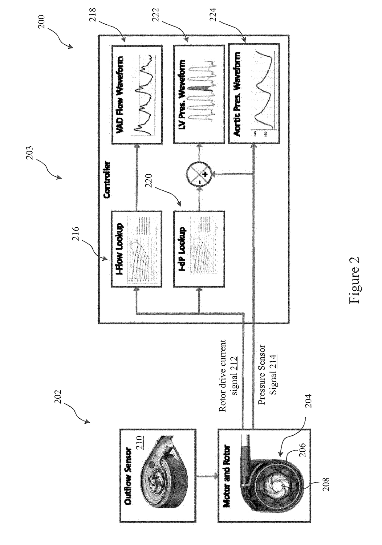
[0025]FIG. 1 illustrates an exemplary method 100 for estimating physiological waveforms of interest of a patient with a blood pump according to some embodiments. The method 100 may include receiving a rotor drive current signal of the blood pump 102. A pressure sensor signal that is associated with an input or an output of the blood pump may also be received 104. A differential pressure across the blood pump may be calculated based on the received rotor drive current signal 106. A physiological waveform of the patient may be calculated based on the received pressure sensor signal and the differential pressure across the blood pump 108. Thereafter, the calculated physiological waveform may be outputted 110. Additionally, a pumping operation of the blood pump may be adjusted in response to the calculated physiological waveform 112.

[0026]Method 100 may be used to estimate the left ventricular pressure waveform. Additionally, the aortic pressure waveform may be calculated separate from ...


PUM


Abstract

The invention generally relates to heart pump systems. In some embodiments, a pressure sensor is provided with a heart pump, either at the inflow or the outflow of the blood pump. The heart pump may further include a flow estimator based on a rotor drive current signal delivered to the rotor. Based on the rotor drive current signal, a differential pressure across the pump may be calculated. The differential pressure in combination with the pressure measurements from the pressure sensor may be used to calculate pressure on the opposite side of the pump from the pressure sensor. In some embodiments, the pressure sensor is located at the outflow of the pump and the pump is coupled with the left ventricle. The differential pressure and pressure measurement may be used to calculate a left ventricular pressure waveform of the patient. With such a measurement, other physiological parameters may be derived.

Description

CROSS-REFERENCE TO RELATED APPLICATIONS[0001]The present application claims the benefit of U.S. Provisional Application No. 62 / 478,492, filed Mar. 29, 2017, the entire contents of which are hereby incorporated by reference herein.BACKGROUND[0002]Heart disease is a growing epidemic in the United States that can lead to heart failure. Heart failure is characterized as a progressive, downward spiral in heart function. In particular, cardiac injury can cause cardiac dysfunction, which results in reduced cardiac output. Some results of reduced cardiac output are endothelial dysfunction, neurohormonal activation, renal impairment, and vasoconstriction. These results can lead to fluid retention and increased systemic vascular resistance. An increase in systemic vascular resistance can create increased cardiac load which can cause further cardiac dysfunction. Thus a cycle of further cardiac dysfunction can be established.[0003]Although there are various treatments proposed and being develop...

Claims


Application Information

Patent Timeline
IPC IPC(8): A61M1/10A61B5/029A61M1/12A61B5/00A61M60/178A61M60/221A61M60/232A61M60/237A61M60/422A61M60/531A61M60/546A61M60/88
CPCA61M1/1086A61B5/029A61M1/122A61B5/0031A61B5/02405A61M2205/3334A61M1/127A61M2205/3507A61M1/1036A61M2210/125A61M60/546A61M60/88A61M60/232A61M60/422A61M60/237A61M60/178A61M60/531A61M60/221A61M60/148A61M60/419
Inventor HARJES, DANIEL I.FREDERICK, KATHRYN B.LEE, ERIC
Owner TC1 LLC
Learn More