
Face Down MLCC

a technology of ceramic capacitors and face-down mlcc, which is applied in the field of multi-layered ceramic capacitors, can solve the problems of mlcc's manufactured with polarized dielectrics, such as barium titanate, being prone to microphonic noise, manufacturing steps, and producing audible noise, so as to reduce the space requirement

Inactive Publication Date: 2018-09-06
KEMET ELECTRONICS CORP
View PDF0 Cites 0 Cited by
  • Summary
  • Abstract
  • Description
  • Claims
  • Application Information

AI Technical Summary

Benefits of technology

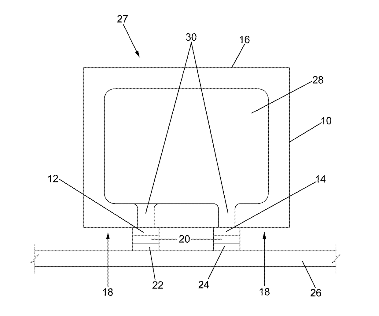
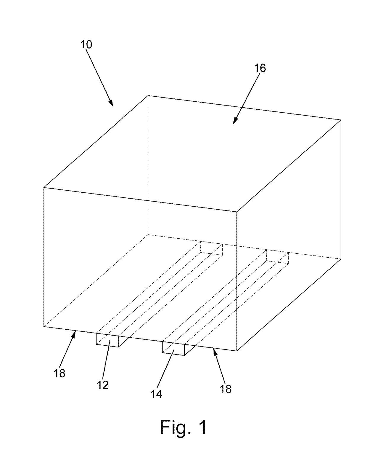
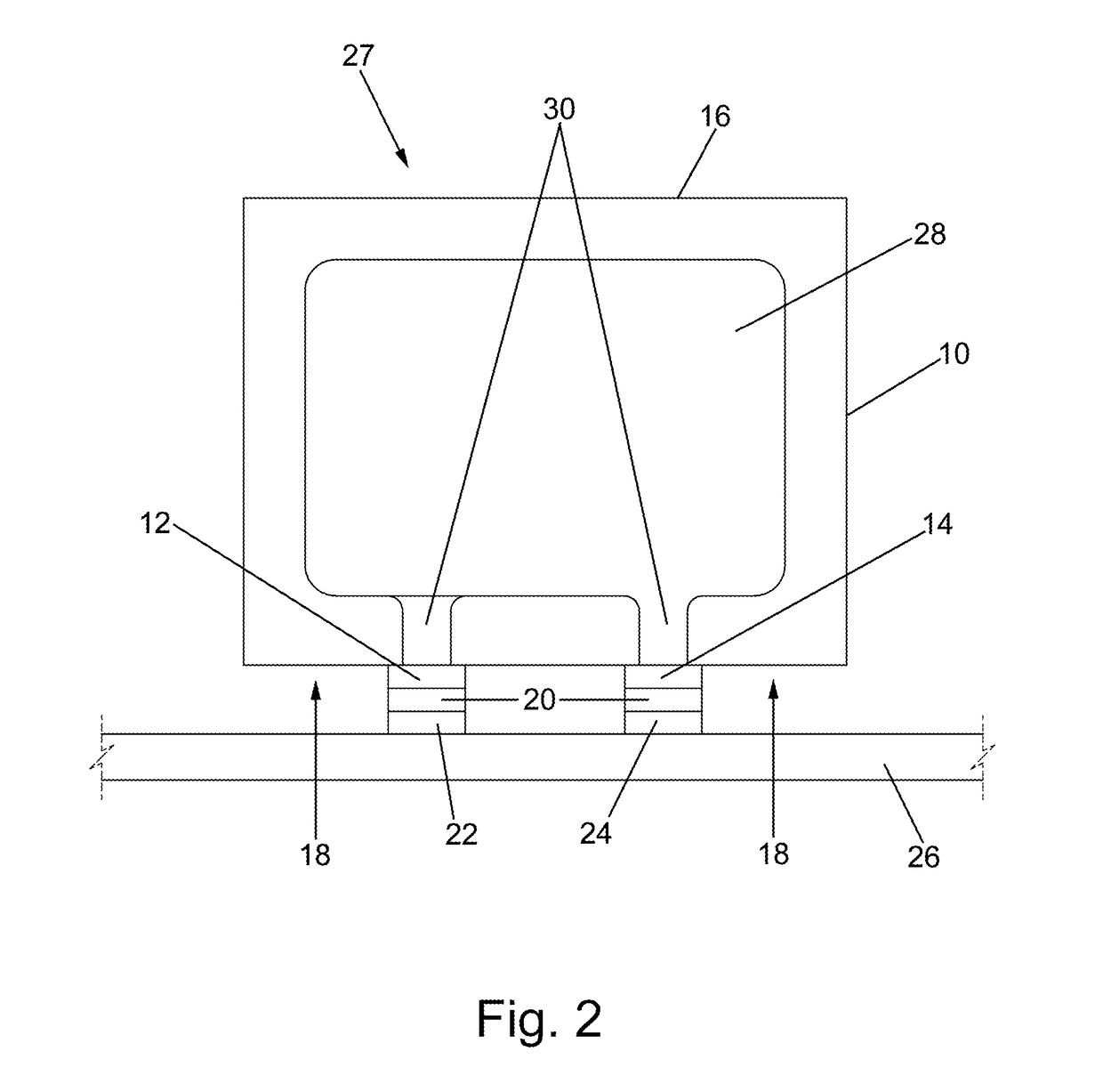
The present invention is about a type of ceramic capacitor that can be mounted without leads and has very low noise levels. The invention has a specific structure that reduces the space requirement of the capacitor and eliminates noise in certain frequencies. The ceramic capacitor can be attached to a circuit board and connected to circuit traces on the board to form an electrical component. The technical effects of this invention include improved performance and reduced size and noise levels of the ceramic capacitor.

Problems solved by technology

Multilayer ceramic capacitors, or MLCC's, manufactured with polarized dielectrics, such as barium titanate, are prone to microphonic noise.
The ceramic movement can be magnified by the circuit board on which the component is mounted ultimately producing an audible noise when an electric field is applied.
Leads mitigate the microphonic noise, however, leads are contradictory to the ever present desire for miniaturization, simplification, reduced manufacturing steps and reduced cost.
With leadless capacitors, and particularly leadless stacks of capacitors mounted on a circuit board, microphonic noise can be enhanced which is highly undesirable, particularly, in portable devices such as cell phones and the like.
While beneficial, these techniques still result in some microphonic noise, especially, if a multiplicity of capacitors are electrically coupled and the vibrations can be coupled or harmonic.

Method used


Image

  • Face Down MLCC
  • Face Down MLCC
  • Face Down MLCC

Examples


Embodiment Construction

[0080]A series of conventional capacitors was prepared using barium titanate ceramic. The body of the capacitors was 6.47 mm (0.2549 inches) long 1.78 mm (0.071 inches) wide. The capacitors were identical except for the spacing of the external terminations which were spaced as detailed in Table 1 wherein the termination separation and spacing ratio and average decibels (dBA) are provided.

TABLE 1TerminationSpacingSpacingRatio(mm)dBA1.0006.47670.7114.60640.4162.69580.1210.78057

[0081]As realized from the results presented in Table 1, a significant reduction in noise is observed as indicated by as much as 10-fold reduction in the noise propagation as indicated in decibels which is logarithmic. The results of the noise testing illustrated that a spacing / chip length ratio of below 0.6, and preferably below 0.5 is sufficient to reduce the noise level by many orders of magnitude.

[0082]The invention has been described with reference to the preferred embodiments without limit thereto. Additio...


PUM

PropertyMeasurementUnit
Lengthaaaaaaaaaa
Lengthaaaaaaaaaa
Lengthaaaaaaaaaa

Abstract

An multilayered ceramic capacitor is provided with mitigated microphonic noise propagation. The multilayered ceramic capacitor comprising a body comprising at least one face wherein the face has a body length. Parallel internal electrodes of alternating polarity are in the body wherein each internal electrode has a tab integral thereto wherein adjacent tabs are not in registration and alternate tabs are in registration. A dielectric is between adjacent internal electrodes. External terminations wherein a first external termination are in electrical contact with first tabs in registration and a second external termination is in electrical contact with second tabs in registration wherein the first external termination and second external termination are on the face and separated by a termination separation. A ratio of the termination separation to the body length is no more than 0.6 and the body comprises an extended portion beyond the external terminations.

Description

CROSS-REFERENCE TO RELATED APPLICATIONS[0001]The present application claims priority to pending U.S. Provisional Application No. 62 / 422,223 filed Nov. 15, 2016 which is incorporated herein by reference.BACKGROUND[0002]The present invention is related to electronic components and methods of making electronic components. More specifically, the present invention is related to multilayered ceramic capacitors with reduced microphonic noise achieved through structural and mounting improvements.[0003]Multilayer ceramic capacitors, or MLCC's, manufactured with polarized dielectrics, such as barium titanate, are prone to microphonic noise. Microphonic noise is believed to be caused by the electrostriction, also referred to as the piezoelectric effect, which is the movement of ceramic that occurs in the presence of an applied electric filed. The ceramic movement can be magnified by the circuit board on which the component is mounted ultimately producing an audible noise when an electric field...

Claims


Application Information

Patent Timeline
IPC IPC(8): H01G4/30H05K1/11H04R19/04H05K1/09H05K1/18H01G4/12H01G4/228H01G4/012H05K3/34
CPCH05K1/111H04R2410/03H05K2201/10015H04R19/04H05K1/09H01G4/30H04R2307/023H05K1/181H01G4/1227H01G4/228H01G4/012H05K3/341H01G4/232H05K3/3431H01G9/00H01G9/0029H01G9/008H01G9/048
Inventor VAUGHAN, RANDAL J.CROSBY, GREGORY L.GURAV, ABHIJIT
Owner KEMET ELECTRONICS CORP
Learn More