Vehicle drive system

a technology of drive system and vehicle, which is applied in the direction of braking system, braking components, transportation and packaging, etc., can solve the problems of reduced running stability, unbalanced left wheel and right wheel brake for

Active Publication Date: 2018-08-23
TOYOTA JIDOSHA KK
View PDF10 Cites 10 Cited by
  • Summary
  • Abstract
  • Description
  • Claims
  • Application Information

AI Technical Summary

Benefits of technology

[0024]Thus, according to one aspect of the present disclosure, the first controller controls the pair of the front wheels, and the second controller controls the pair of the rear wheels. As described, only the brake device of the one of the first brake system and the second brake system generates the brake torque to be applied to the pair of front wheels or the pair of rear wheels in the event of failure in the other brake system. In the vehicle drive system, therefore, the brake force can be applied to the vehicle even in the event of failure of one of the brake systems while preventing a reduction in the running stability resulting from yawing or the like.
[0025]According to another aspect of the present disclosure, the third controller controls one of the diagonal pairs of wheels, and the fourth controller controls the other diagonal pairs of wheels. As described, only the brake device of the one of the third brake system and the fourth brake system generates the brake torque to be applied to one of the diagonal pairs of wheels in the event of failure in the other brake system. In the vehicle drive system, therefore, the brake force can be applied to the vehicle even in the event of failure of one of the brake systems while preventing a reduction in the running stability resulting from yawing or the like.

Problems solved by technology

In addition, unsprung load may be increased by the brake devices attached to the wheels and hence running stability may be reduced.
Further, the brake forces applied to the right wheel and the left wheel may be unbalanced in the event of failure of the brake device(s).

Method used


Image

  • Vehicle drive system
  • Vehicle drive system
  • Vehicle drive system

Examples


Embodiment Construction

)

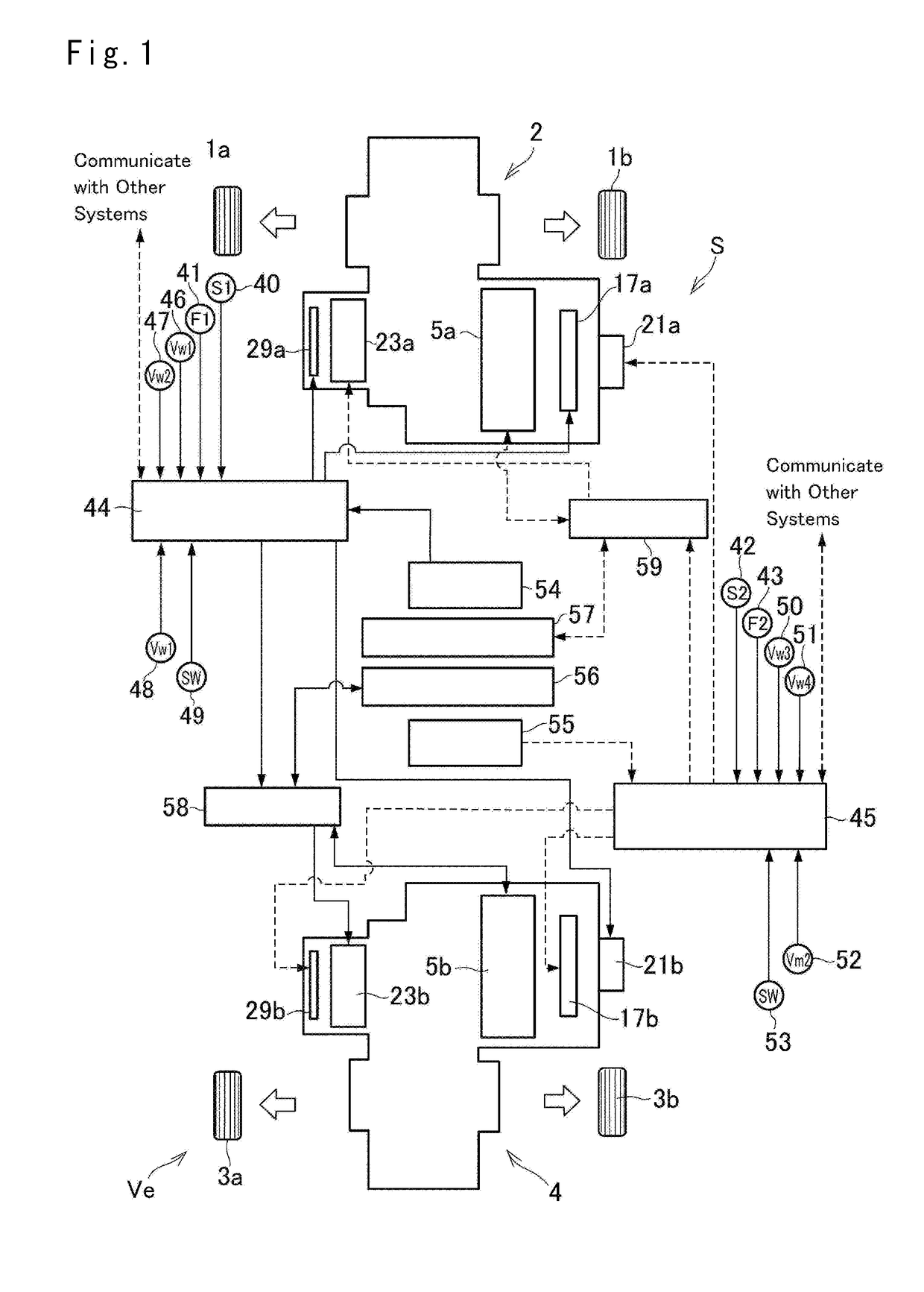
[0037]Embodiments of the present disclosure will now be explained with reference to the accompanying drawings. Referring now to FIG. 1, there is schematically shown a structure of a vehicle drive system S. The vehicle drive system S comprises: a first drive unit 2 that controls a drive force and a brake force applied to a pair of front wheels 1a and 1b; and a second drive unit 4 that controls a drive force and a brake force applied to a pair of a pair of rear wheels 3a and 3b. Here, structures of the drive units 2 and 4 are substantially identical to each other, therefore, only the structure of the first drive unit 3 will be described below and detailed explanation for the second drive unit 4 is omitted.

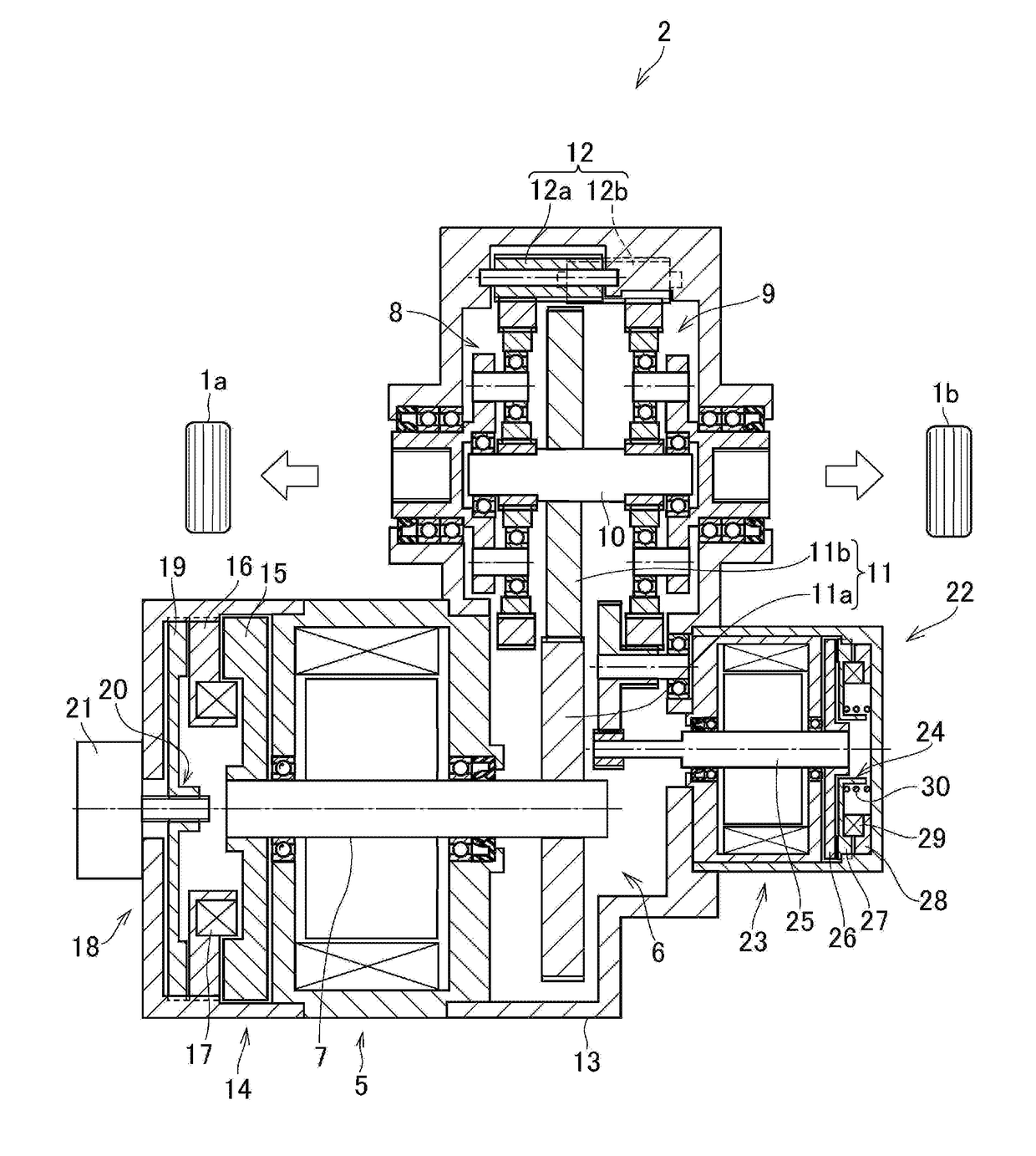
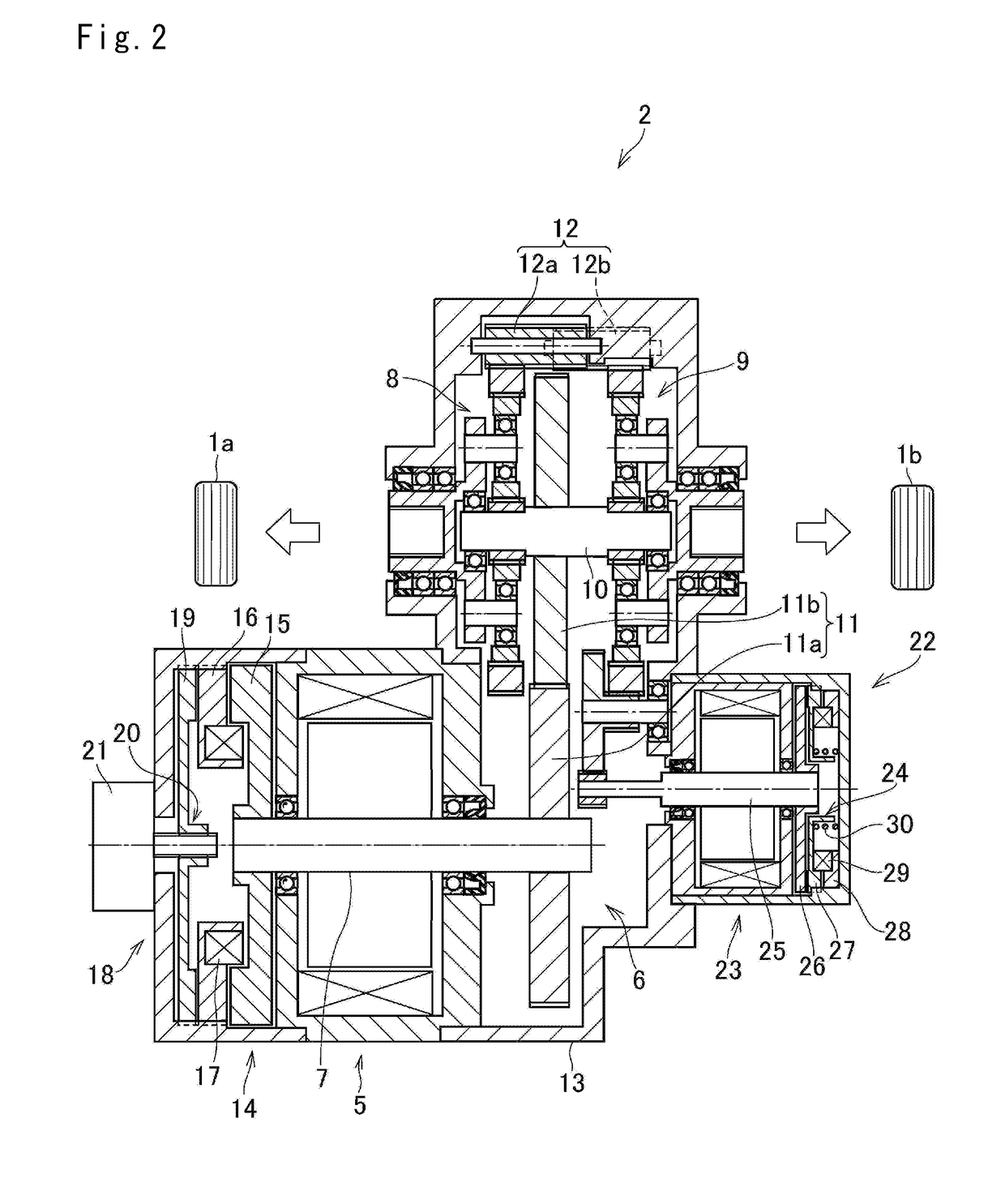
[0038]Turning to FIG. 2, there is shown a structure of the first drive unit 2. In the first drive unit 2, a drive motor 5 is connected to a transmission mechanism 6. For example, a permanent magnet synchronous motor and an induction motor may be used as the drive motor 5, and the dr...


PUM


Abstract

A vehicle drive system that ensures brake force in the event of failure of a brake device or a controller. In vehicle drive system, a first brake device applies a brake torque to a pair of front wheels and a second brake device applies a brake torque to a pair of rear wheels. A first brake system includes a first controller and the first brake device, and a second brake system includes a second controller and the second brake device. In the event of occurrence of failure in one of the first brake system and the second brake system, only the other brake system generates brake torque.

Description

CROSS REFERENCE TO RELATED APPLICATIONS[0001]The present disclosure claims the benefit of Japanese Patent Application No. 2017-030463 filed on Feb. 21, 2017 with the Japanese Patent Office, the disclosure of which are incorporated herein by reference in its entirety.BACKGROUNDField of the Disclosure[0002]Embodiments of the present application relate to the art of a drive system for vehicles comprising a plurality of brake units to apply a brake torque individually to each wheel.Discussion of the Related Art[0003]WO 96 / 16831 A1 describes a vehicle control system comprising a drive motor and a mechanical braking device. The control system taught by WO 96 / 16831 is configured to establish a regenerative torque by a drive motor and establish a brake torque by the mechanical braking device when a brake pedal is depressed. According to the teachings of WO 96 / 16831, specifically, information about an operation of the brake is transmitted to a management controller, and the regenerative torq...

Claims


Application Information

Patent Timeline
Patent Type & Authority Applications(United States)
IPC IPC(8): B60L7/26F16D65/18B60T13/74B60T8/171B60T1/06B60L7/18
CPCB60L7/26F16D65/18B60T13/741B60T13/746B60T8/171B60T1/065B60L7/18F16D2125/50B60T2270/604B60T2270/403B60T13/00F16H57/10F16H63/34B60T1/10B60T8/1766B60T8/885B60T13/662F16D61/00Y02T10/72
Inventor ISONO, HIROSHI
Owner TOYOTA JIDOSHA KK
Why Eureka
Try Eureka