
Fastener delivery apparatus

a technology of fasteners and fasteners, which is applied in the direction of metal-working apparatuses, nailing tools, stapling tools, etc., can solve the problems of significant increase in tube wear, and fastener to jam in the tube, so as to reduce the friction between the fastener and the wall, reduce the tendency of fasteners to jam, and reduce the motive force

Inactive Publication Date: 2005-10-04
ATLAS COPCO IAS UK LIMITED +1
View PDF13 Cites 31 Cited by
  • Summary
  • Abstract
  • Description
  • Claims
  • Application Information

AI Technical Summary

Benefits of technology

[0009]According to the present invention there is provided a fastener delivery apparatus comprising a fastener delivery tube connected between a supply of fasteners and a setting tool of a fastener machine, the tube having an internal cross-section configured to conform substantially to the size and shape of the fastener to be used and connected to a source of pressurized gas, wherein the source of pressurized gas has a supply bore with an interior shape and dimension that is substantially equal to an interior dimension and shape of the delivery tube and wherein the supply of fasteners is connected to the delivery tube via a sealable passage that may be sealed so as to prevent leakage of gas from the delivery tube.
[0010]By ensuring that the size and shape of the pressurized gas outlet bore and the delivery tube are matched, there is a significant reduction in turbulence of the pressurized gas. This ensures that the flow of gas remains smooth and laminar thereby preventing fasteners from being thrown against walls of the delivery tube and losing momentum as they travel along the tube. Lubrication of the tube is therefore not required and feeding of a plurality of rivets at once becomes feasible. In addition, the sealed passage reduces the leakage of gas from the apparatus. This feature enables the compressed gas to be supplied at significantly lower pressures, such as 2 bar or less, than is currently possible. The profile of the fastener in the tube provides an effective seal and the smooth laminar flow of the gas reduces its contact with the wall of the delivery tube. In reducing the gas pressure required to transport the rivet the running cost of the apparatus is significantly reduced. Moreover, noise pollution is significantly reduced. The use of a sealed passage provides a barrier against the ingress of dirt and ensures that the pressurized gas supply is used efficiently by directing all of the supplied gas towards the fastener.
[0011]Such apparatus also achieves consistent, repeatable minimum transport times for each given design of fastener allowing the full process cycle, e.g. feeding and riveting, to be efficiently implemented at as high a rate as possible.
[0012]The present invention lies partly in the realization that the flow rate of the pressurized gas is more important than the gas pressure in transporting fasteners and that it is more efficient to introduce a fastener into the path of a pressurized gas jet rather than to direct the gas towards the fastener in the tube via branch tubes or the like.
[0015]Preferably the sealable passage is sealable by a gate having an internal cross-section that is substantially matched in terms of shape and dimension to the internal cross-section of the delivery tube so as to reduce turbulence or drag to the flow of gas passing it.
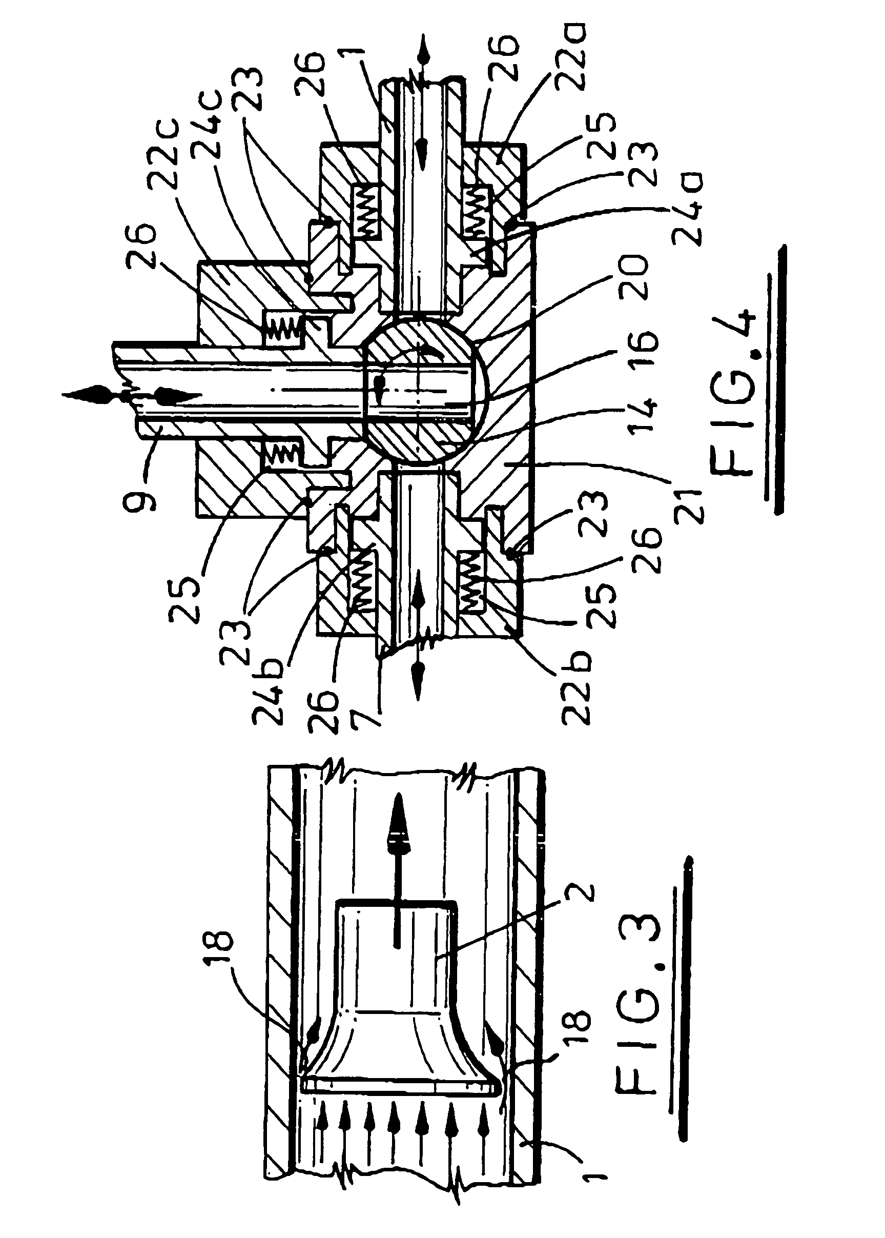
[0017]Advantageously the delivery tube is of a size such that, in use, there is clearance between the fastener and the tube so as to provide a gas cushion around the fastener. This reduces the friction between the fastener and walls of the delivery tube and also reduces the tendency of the fastener to jam in the tube. These advantages outweigh any reduction of motive force due to air leakage past the fastener.

Problems solved by technology

There are several problems associated with compressed air delivery tubes of the kind described above.
First, there is a tendency for fasteners to jam in the tube.
It is often desirable to be able to transport a plurality of fasteners at once along a delivery tube but this significantly increases the tendency to jam.
Secondly friction between the fasteners and the tubes causes tube wear.
Delivery tubes have to be inspected at regular intervals for wear as a worn tube may be susceptible to blockages or slower feed rates causing increased cycle times. Moreover, wear often results in accumulation in the delivery tube of external dirt, dust or moisture or trace particles of the fastener, fastener coating or tube and they may also cause blockages and slower feed rates.
Compressed air pressure normally decreases along the length of the delivery tube owing to losses (such as for example leaks or friction losses).
The increase in air pressure and the addition of booster points increases air turbulence within the tube.
If the flow of air is not as smooth as possible there is an increased tendency for fastener jams and the resultant scraping contact can in turn cause wear in the tube.
The decreasing air-pressure owing to losses can also cause heavier fasteners to lose momentum so that they fail to reach the end of their journey with sufficient speed unless compressed air booster points are employed.
However, over a period of use the ingress of dirt can result in the tube becoming clogged by a paste comprising the combination of the dirt or trace particles and lubrication oil or moisture.
A further disadvantage is that known systems may require the continuous application of such air pressure at 5–6 bar to maintain effective performance, as opposed to controlled blasts.
Moreover, owing to the above limitations, known systems cannot reliably feed fasteners over long distances, the maximum possible tube lengths being typically 8 m–15 m.

Method used


Image

  • Fastener delivery apparatus
  • Fastener delivery apparatus
  • Fastener delivery apparatus

Examples


Embodiment Construction

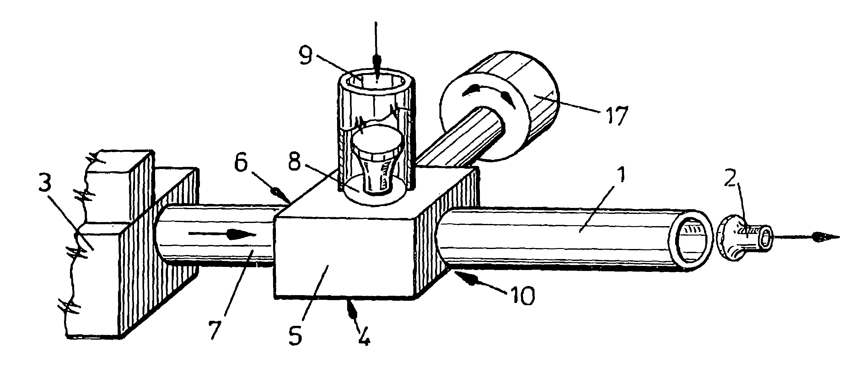
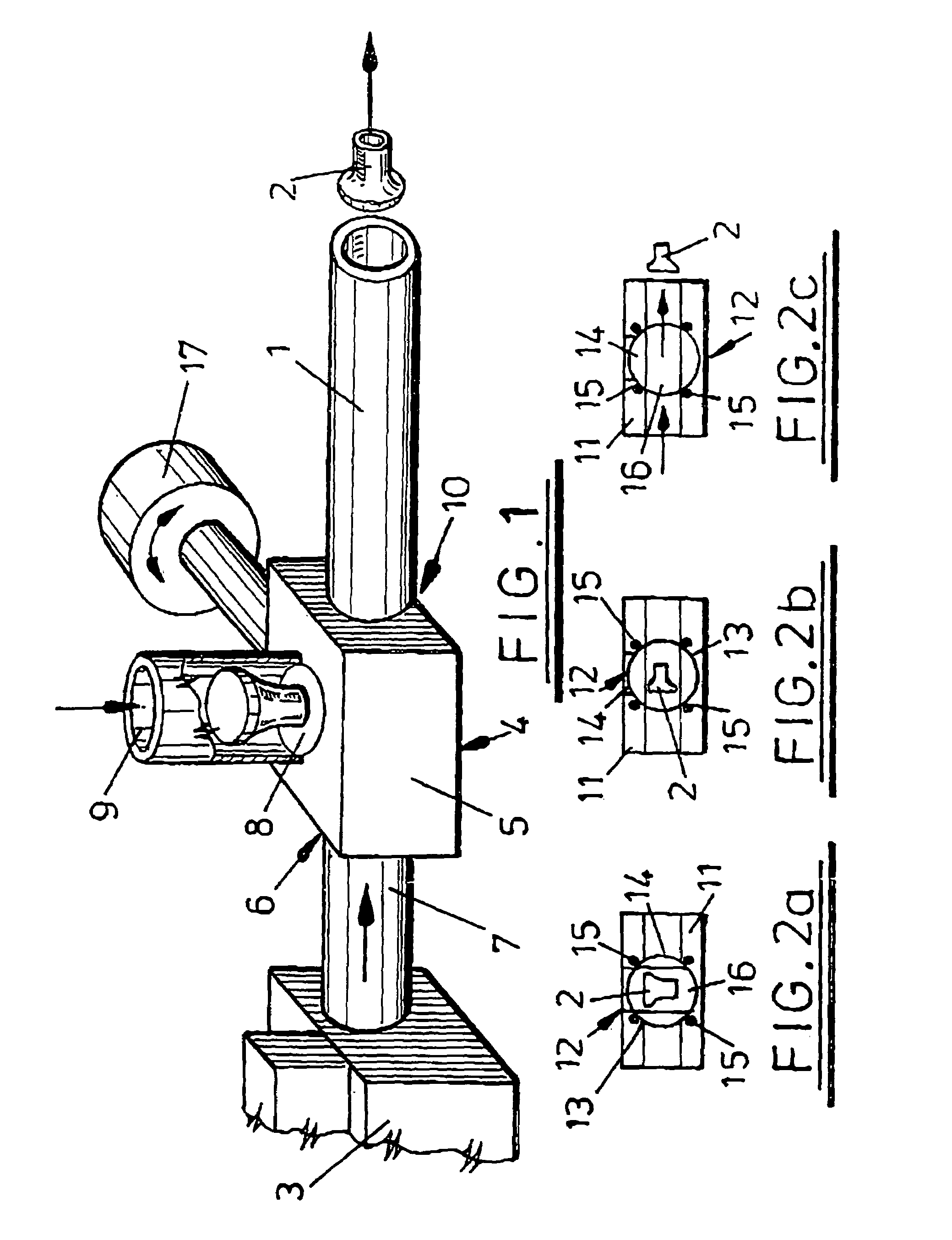
[0023]Referring now to the FIG. 1 of drawings, there is shown apparatus for transferring rivets from a central rivet supply to the nose of a rivet setting machine (neither of which are shown in the drawings).

[0024]The apparatus comprises a rivet delivery tube 1 in which rivets 2 are transported individually or in groups between the supply and the nose of the rivet setting machine, a compressed air supply 3 connected to one end of the delivery tube 1 and a rivet transfer gate assembly 4 disposed in close proximity to the compressed air supply 3. The transfer gate assembly 4 comprises a housing 5 with a first inlet aperture 6 connected to an outlet tube 7 of the compressed air supply 3, a second inlet aperture 8 connected to the end of a feeder tube 9 from the rivet supply and an outlet aperture 10 connected to the delivery tube 1.

[0025]The interior of the housing 11, shown in FIGS. 2a to 2c, has a tube portion interconnecting the delivery tube 1 and the outlet tube 7 of the compresse...


PUM

PropertyMeasurementUnit
Pressureaaaaaaaaaa
Pressureaaaaaaaaaa
Sizeaaaaaaaaaa

Abstract

A fastener delivery tube (1) is connected between a supply of fasteners, such as rivets (2), and the nose of a fastener setting machine. The delivery tube (1) is connected to an outlet tube (7) of a source of compressed air (3), the outlet tube (7) having an internal bore substantially equal in size to the internal bore of the delivery tube (1). The supply of fasteners is connected to the delivery tube via a feeder tube (9) and transfer gate (4). The transfer gate (4) is sealed so as to prevent leakage of air from the delivery tube (1). The arrangement reduces turbulence in the delivery tube (1) ensures that friction between the fastener (2) and the tube (1) is reduced and permits compressed air to be supplied at significantly lower pressure than has heretofore been possible.

Description

FIELD OF THE INVENTION[0001]The present invention relates to fastener delivery apparatus and more particularly, but not exclusively to delivery apparatus for transferring rivets from a supply to a setting tool of a riveting machine.BACKGROUND OF THE INVENTION[0002]The term “fastener” is used herein to describe rivets, screws, slugs or other types of fastening devices.[0003]It is well known to distribute rivets or other fasteners (e.g. studs, nuts, bolts) between a supply and a setting tool of a riveting machine or setting tooling within a press by conveying them individually in delivery tubes by compressed air propulsion. A delivery tube of this kind typically has an internal passageway that is configured to conform closely to the shape of the fastener. Additional compressed air may be admitted into the tube at one or more locations along the length of the tube by means, for example, of T-junctions, branch tubes, or elbows connected between a supply of compressed air and the deliver...

Claims


Application Information

Patent Timeline
IPC IPC(8): B21J15/00B21J15/32B23P19/00
CPCB21J15/32B23P19/003B23P19/005
Inventor COGLEY, KEVINBARFIELD, PHILIP JOHN
Owner ATLAS COPCO IAS UK LIMITED
Learn More