
Tool changing method and tool changer

Active Publication Date: 2018-08-09
MAKINO MILLING MASCH CO LTD
View PDF0 Cites 6 Cited by
  • Summary
  • Abstract
  • Description
  • Claims
  • Application Information

AI Technical Summary

Benefits of technology

The invention is a tool changer that can adjust the opening and closing of the tool changing arm based on the tool length or diameter. This reduces the time needed to change tools. The invention uses an image capturing device to determine the tool length and adjust the operation parameter of the changing arm accordingly. This ensures safe and efficient tool changes and reduces damage to the tools and the door.

Problems solved by technology

Therefore, it should be troublesome to input the tool lengths into the storage device, and if incorrect tool lengths are input, a tool and the door may interferes with each other when changing tools, resulting in damage in the tool and / or the door.

Method used


Image

  • Tool changing method and tool changer
  • Tool changing method and tool changer
  • Tool changing method and tool changer

Examples


Embodiment Construction

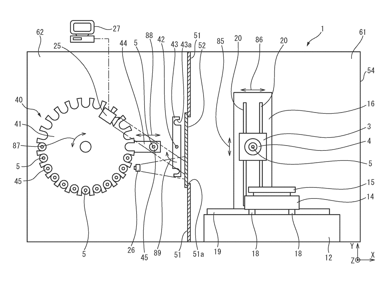
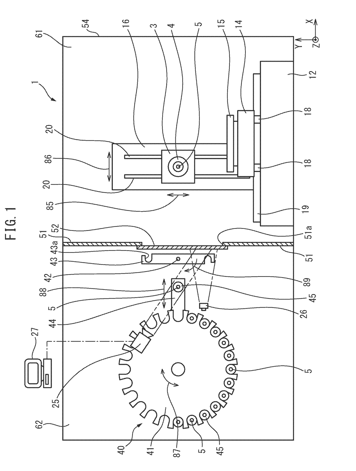
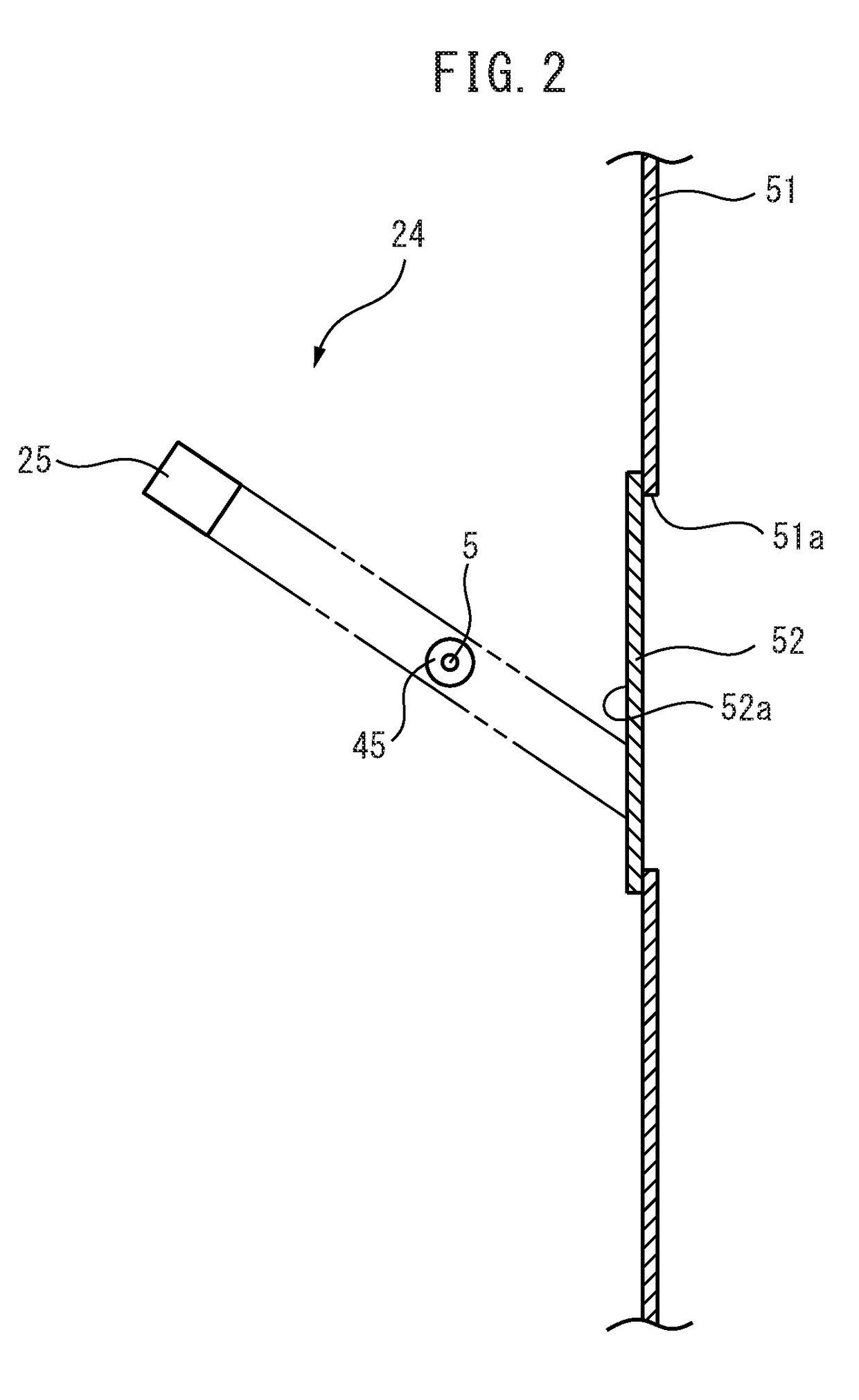
[0029]With reference to FIGS. 1-3, a preferred embodiment of the present invention will be described. FIG. 1 is schematic section of a machine tool provided with a tool changer according to a first embodiment. FIG. 2 is a schematic section of an image capturing device provided in the tool changer of FIG. 1. FIG. 3 is a schematic front view of the image capturing device of FIG. 2. In FIGS. 1-3, a tool 5 held by a tool shifter 44 is positioned at a standby position for the tool.

[0030]The machine tool 1 is a horizontal machining center in which a tool and a workpiece are automatically moved relative to each other based on a machining program. The machine tool 1 is provided with a feed device configured to move a tool and a workpiece relative to each other. The feed device moves the workpiece in directions of a plurality of moving axes. The plurality of feeding axes include three orthogonal linear feed axes of X-, Y- and Z-axes.

[0031]The machine tool 1 includes a bed 12 providing a base...


PUM


Abstract

This tool exchange device for a machine tool uses an exchange arm to exchange tools between a processing area and a tool accommodation area which are partitioned by a partition wall provided with an opening and a shutter capable of opening and closing the opening. In the tool exchange device, an imaging device is used to capture an image of a tool in the tool accommodation area, the length of the tool is calculated from the captured image of the tool, the opening width of the shutter is determined in accordance with the length of the tool, and the shutter is opened to the determined opening width.

Description

CROSS-REFERENCE TO RELATED APPLICATIONS[0001]This application is a U.S. national phase patent application of International Patent Application No. PCT / JP2015 / 071567, filed Jul. 29, 2015, the contents of which is hereby incorporated by reference in the present disclosure in its entirety.FIELD OF THE INVENTION[0002]The invention relates to a tool changing method and a tool changer.BACKGROUND OF THE INVENTION[0003]Patent Literature 1 describes a tool changer configured to change tools, through an opening in a splashguard which defines a machining space, between a machining tool and a tool magazine disposed outside the machining space, in which the opening / closing stroke of a door provided at the opening depending on the tool lengths or the tool diameters of the tools to be changed.PATENT PUBLICATIONS[0004]Patent Literature 1: JP-A-2010-228063BRIEF SUMMARY OF THE INVENTION[0005]According to the tool changer of Patent Literature 1, the opening / closing stroke can be adjusted depending on t...

Claims


Application Information

Patent Timeline
IPC IPC(8): B23Q3/157B23Q17/24
CPCB23Q3/15722B23Q17/2409B23Q2003/15528B23Q3/15534B23Q11/0825B23Q3/15513B23Q11/08B23Q17/2461B23Q2003/1553B23Q2003/155425Y10T483/115Y10T483/10Y10T483/138B23Q3/15503
Inventor KASAHARA, TADASHI
Owner MAKINO MILLING MASCH CO LTD
Learn More