
Printing device and control method for printing device

Active Publication Date: 2020-05-21
SEIKO EPSON CORP
View PDF0 Cites 1 Cited by
  • Summary
  • Abstract
  • Description
  • Claims
  • Application Information

AI Technical Summary

Benefits of technology

The present invention relates to a printing device control method that can print an image on a printing medium using a printing section and a conveying section. The control section can print the image in two modes: a first mode with multiple operations and a second mode after receiving a printing request. In the second mode, the control section can omit or change a part of the operations from the first mode based on the user's requirement. This enables easy customization of the printing image according to the user's needs.

Problems solved by technology

However, concerning the increase in the speed of the first printing after the acquisition of the printing request, Patent Literature 1 does not consider operations other than a warmup operation of the drying mechanism.

Method used


Image

  • Printing device and control method for printing device
  • Printing device and control method for printing device
  • Printing device and control method for printing device

Examples


Embodiment Construction

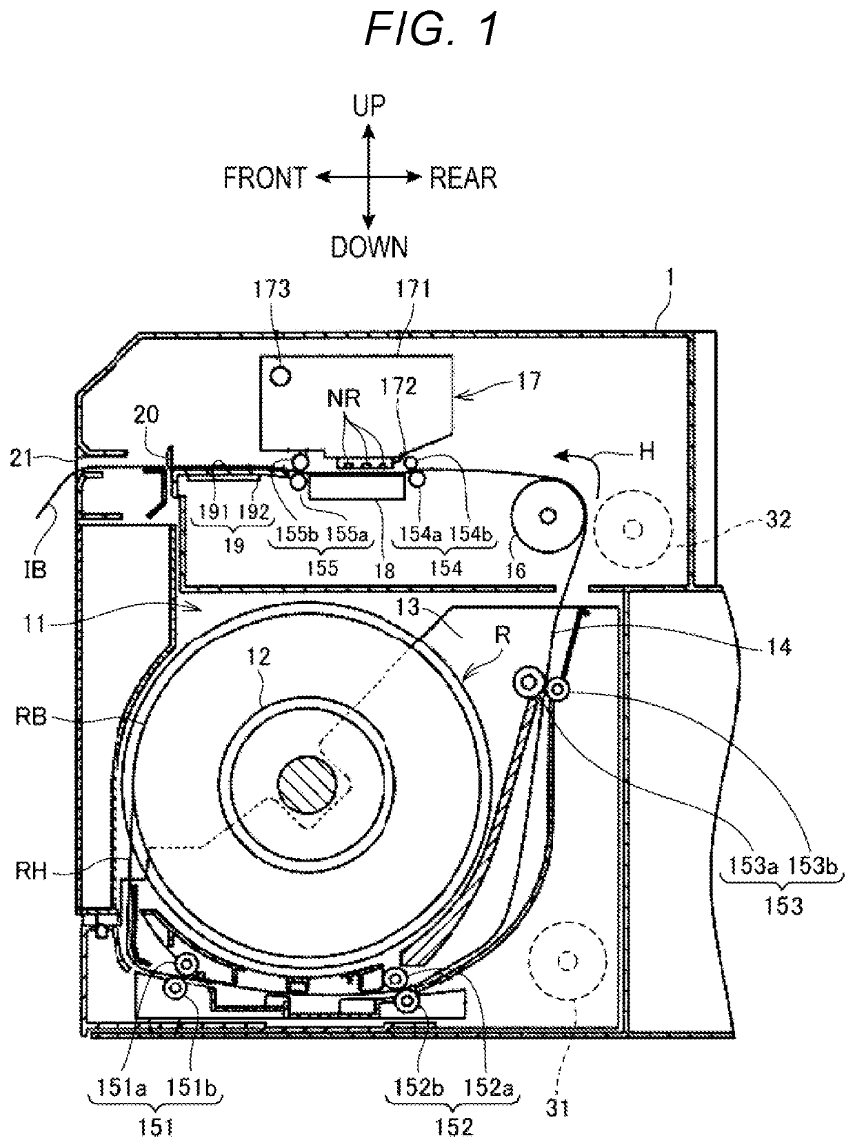
[0018]FIG. 1 is a diagram showing the configuration of a main part of a printing device 1.

[0019]In explanation referring to FIG. 1, as indicated by arrows, a leftward direction in the figure is represented as “front”, a rightward direction in the figure is represented as “rear”, an upward direction in the figure is represented as “upward”, and a downward direction in the figure is represented as “downward”.

[0020]A printing device 1 is a serial inkjet printer. The printing device 1 stores roll paper R, which is a roll-like sheet, lets out the roll paper R, and conveys the roll paper R in a conveying direction H. The roll paper R corresponds to an example of a printing medium. The printing device 1 ejects ink onto the conveyed roll paper R with an inkjet head 172 configured as a serial head and performs printing. The inkjet head 172 corresponds to an example of a printing head.

[0021]As shown in FIG. 1, the printing device 1 includes a roll-paper storing section 11 that stores the roll...


PUM


Abstract

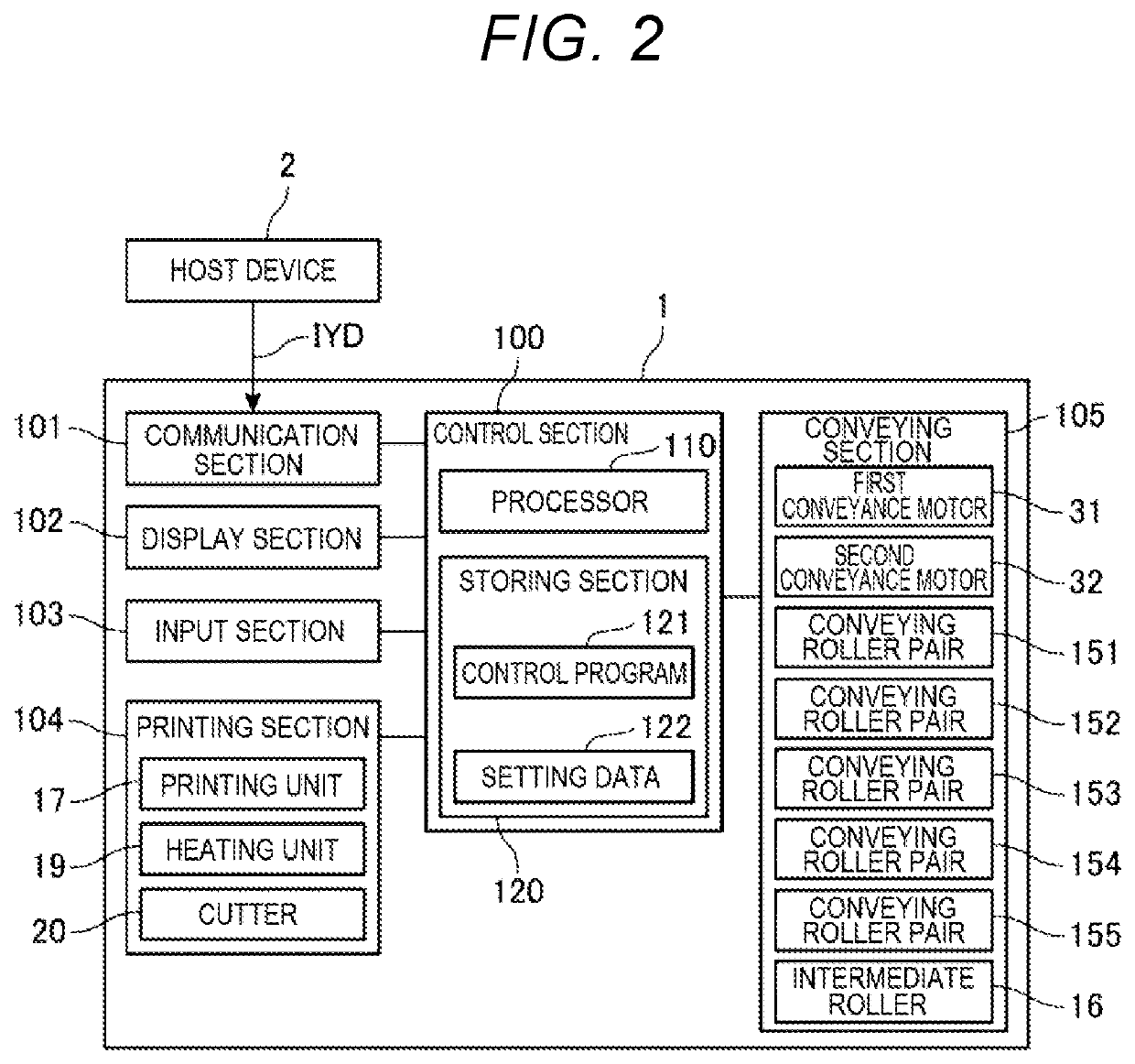
A printing device includes a printing section including an inkjet head configured to eject ink onto a conveyed roll paper, a conveying section configured to convey the conveyed roll paper, and a control section configured to print an image on the conveyed roll paper with the printing section and the conveying section. The control section has a normal printing mode for printing the image with a plurality of operations based on the printing section and the conveying section and a high-speed printing mode for, during first print, printing the image while omitting or changing a part of the plurality of operations included in the normal printing mode according to the operation.

Description

[0001]The present application is based on, and claims priority from JP Application Serial Number 2018-218599, filed Nov. 21, 2018, the disclosure of which is hereby incorporated by reference herein in its entirety.BACKGROUND1. Technical Field[0002]The present disclosure relates to a printing device and a control method for the printing device.2. Related Art[0003]There has been known a device that performs first printing after acquisition of a printing request at high speed. For example, JP A-2001-356616 (Patent Literature 1) discloses a device that, when performing printing of a small number of prints, reduces a warmup time of a drying mechanism to increase the speed of first printing after acquisition of a printing request.[0004]However, concerning the increase in the speed of the first printing after the acquisition of the printing request, Patent Literature 1 does not consider operations other than a warmup operation of the drying mechanism. Therefore, there is room of achieving ...

Claims


Application Information

Patent Timeline
IPC IPC(8): B41J2/045B41J11/00B41J11/70B41J29/38B41J2/165
CPCB41J2/16532B41J2/0451B41J11/007B41J2002/16573B41J11/002B41J11/70B41J29/38B41J2/01B41J15/04B41J11/0024B41J11/00242
Inventor NISHIO, SATORU
Owner SEIKO EPSON CORP
Learn More