
Method and system for manufacturing a transparent body for use in a touch panel

Inactive Publication Date: 2014-08-07
APPLIED MATERIALS INC
View PDF2 Cites 8 Cited by
  • Summary
  • Abstract
  • Description
  • Claims
  • Application Information

AI Technical Summary

Benefits of technology

The present disclosure provides a combination of dielectric films that results in a high-quality transparent body with proper light transmission and stable performance over time. The use of silicon-containing dielectric films and targets allows for a variety of layer stacks, including different types of stacks. This flexibility can reduce the time and cost of manufacturing different types of touch panels.

Problems solved by technology

However, at least some known transparent bodies included in touch screens which are considered robust interfere with a proper transmission of light therethrough due to, for example, thickness, composition, and structure of the layers forming the transparent body.
Furthermore, fabricating such a stable transparent body with high quality, for example with a uniform and defect-free barrier, is challenging.
This procedure is time consuming and can create failures (e.g. a water leak).

Method used


Image

  • Method and system for manufacturing a transparent body for use in a touch panel
  • Method and system for manufacturing a transparent body for use in a touch panel
  • Method and system for manufacturing a transparent body for use in a touch panel

Examples


Embodiment Construction

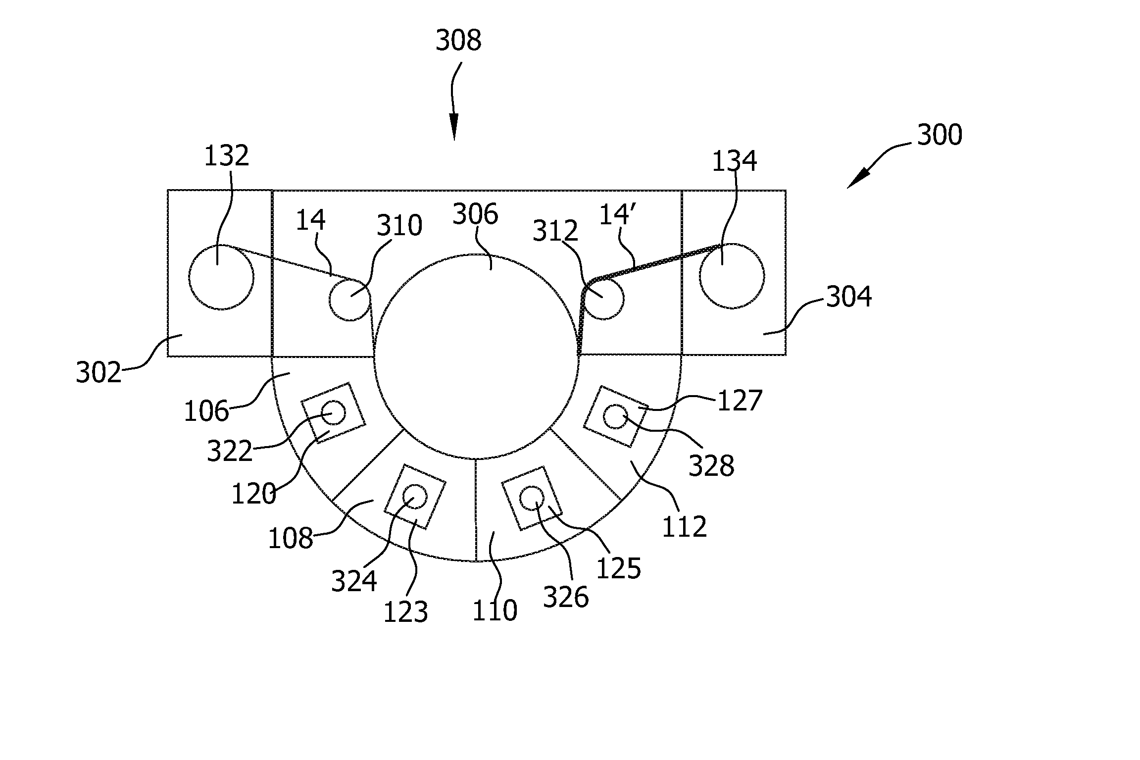
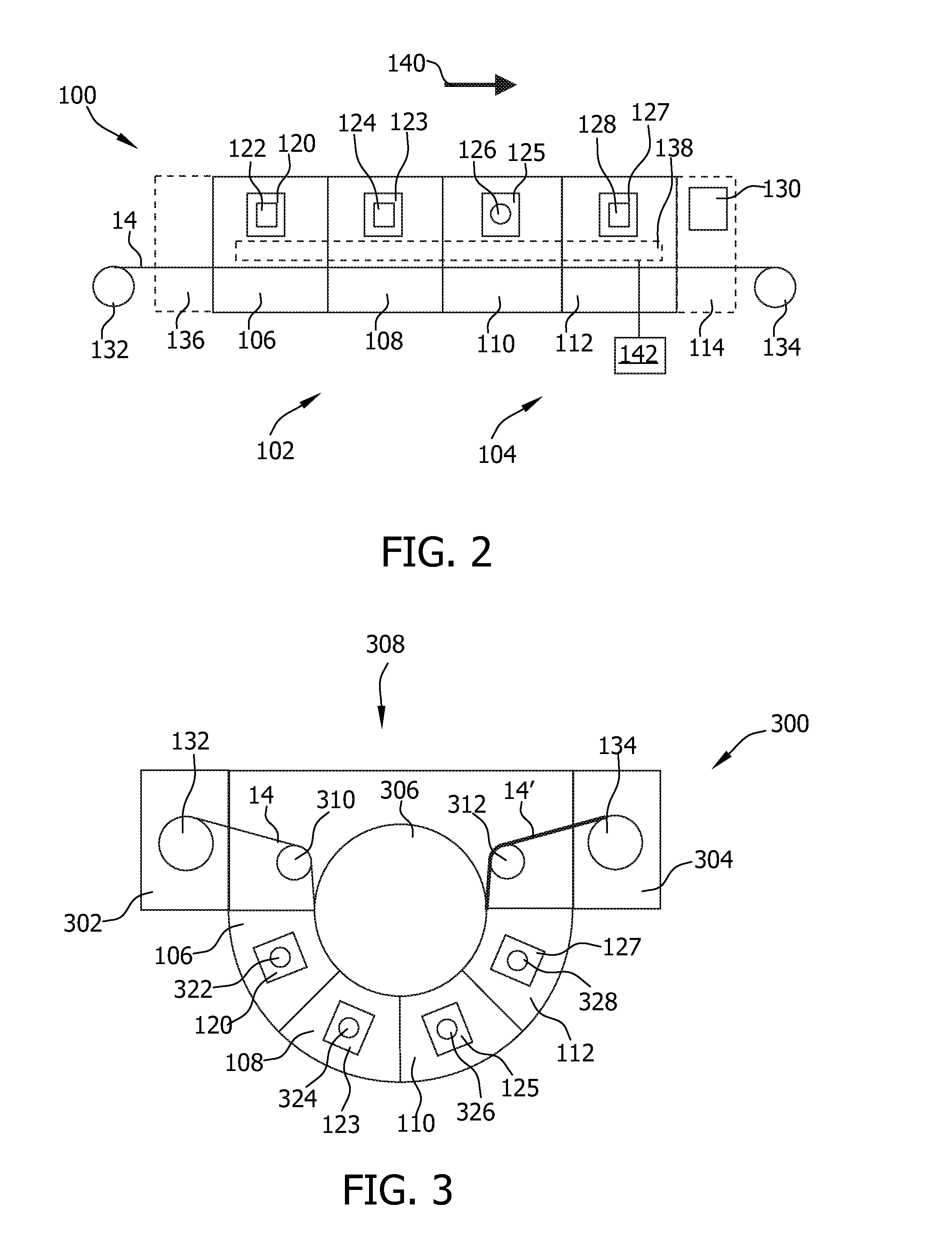
[0023]Reference will now be made in detail to the various embodiments, one ore more examples of which are illustrated in the figures. Each example is provided by way of explanation, and is not meant as a limitation of the invention. It is contemplated that elements of one embodiment may be advantageously utilized in other embodiments without further recitation.

[0024]The embodiments described herein include a process for manufacturing a transparent body for use in a touch panel. In particular, embodiments of the present disclosure include a transparent body including a first transparent stack configured to constitute a barrier in a touch panel and a transparent conductive film configured to constitute a transparent conductor in a touch panel. Thereby, a transparent body according to embodiments herein facilitates touch sensing when implemented in a touch panel.

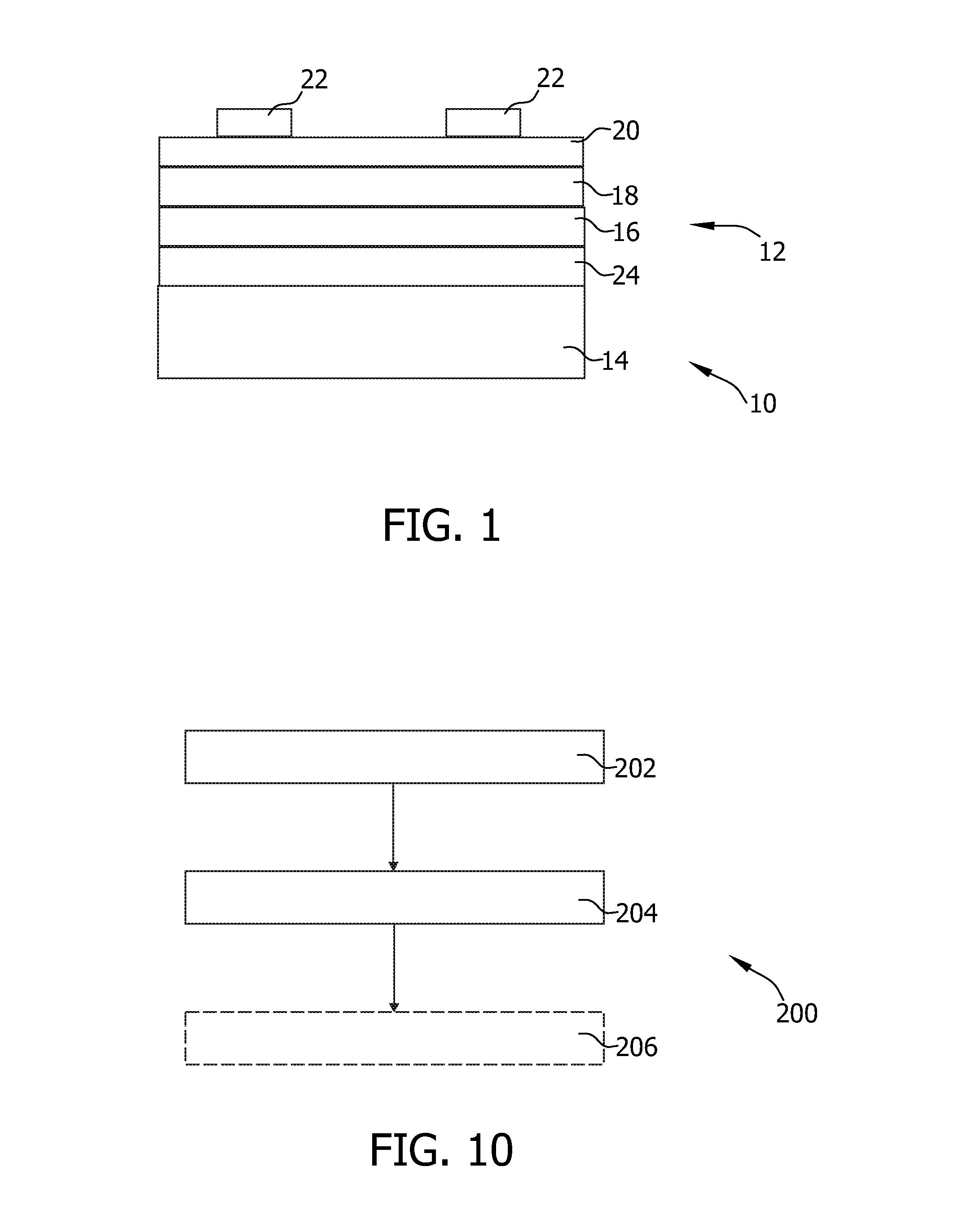
[0025]According to embodiments herein, a first transparent layer stack 12, as depicted in FIG. 1, is deposited over a substra...


PUM

PropertyMeasurementUnit
Weightaaaaaaaaaa
Dielectric polarization enthalpyaaaaaaaaaa
Electrical conductoraaaaaaaaaa

Abstract

A process for manufacturing a transparent body for use in a touch panel is provided. The process includes: The process includes depositing a first transparent layer stack over a substrate with a first silicon-containing dielectric film, a second silicon-containing dielectric film, and a third silicon-containing dielectric film. The first and the third silicon-containing dielectric films have a low refractive index and the second silicon-containing dielectric film has a high refractive index. The process further includes depositing a transparent conductive film in a manner such that the first transparent layer stack and the transparent conductive film are disposed over the substrate in this order. At least one of the first silicon-containing dielectric film, the second silicon-containing dielectric film, the silicon-containing third dielectric film, or the transparent conductive film is deposited by sputtering from a target. Further thereto, a deposition apparatus (300) for manufacturing a transparent body for use in a touch panel and a transparent body for use in a touch panel are provided.

Description

TECHNICAL FIELD[0001]Embodiments of the present disclosure relate to processes and systems for manufacturing a transparent body for use in a touch panel and a transparent body fabricated according to these processes.BACKGROUND ART[0002]Touch panels are a particular class of electronic visual displays, which are able to detect and locate a touch within a display area. Generally, touch panels include a transparent body disposed over a screen and configured to sense a touch. Such a body is substantially transparent, so that light in the visible spectrum emitted by the screen can be transmitted therethrough. At least some known touch panels include a transparent body constituted by a barrier and a transparent conductor formed, in this order, over a substrate. A touch on the display area of such a panel generally results in a measurable change of capacitance in a region of the transparent body. The change in capacitance may be measured using different technologies, so that the position o...

Claims


Application Information

Patent Timeline
IPC IPC(8): H01J37/34C23C14/34
CPCC23C14/3464H01J37/3429G02B1/105G06F2203/04103G02B1/16C23C14/06C23C14/08C23C14/10C23C14/0652
Inventor LOTZ, HANS-GEORG
Owner APPLIED MATERIALS INC
Learn More