Cathode insulator design
a cathode insulator and cathode technology, applied in the field of cathode insulator design, primary lithium electrochemical cells, can solve the problems of premature discharge of cells, one or both of lithium cluster formation and surface plating
- Summary
- Abstract
- Description
- Claims
- Application Information
AI Technical Summary
Benefits of technology
Problems solved by technology
Method used
Image
Examples
example 1
gn
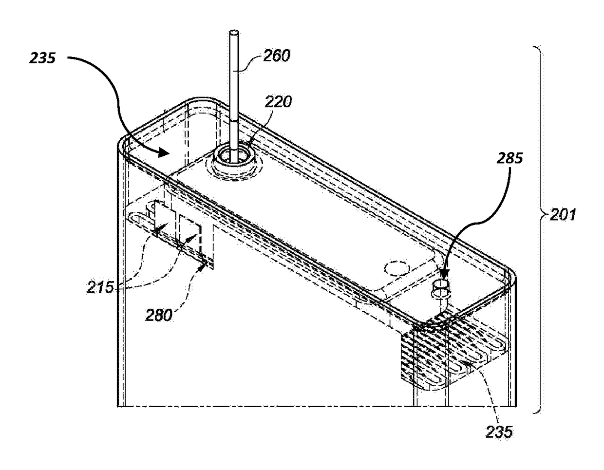
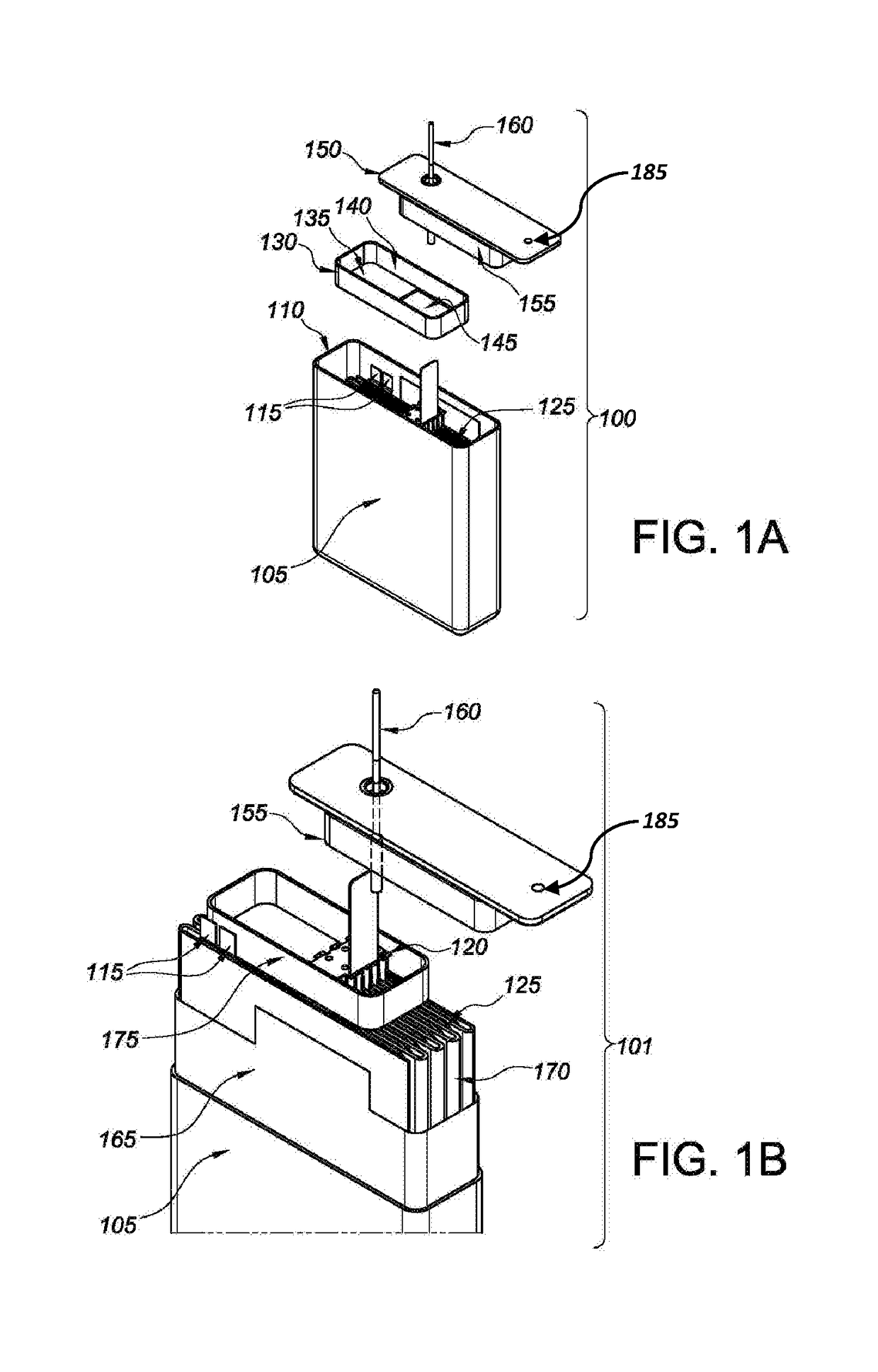
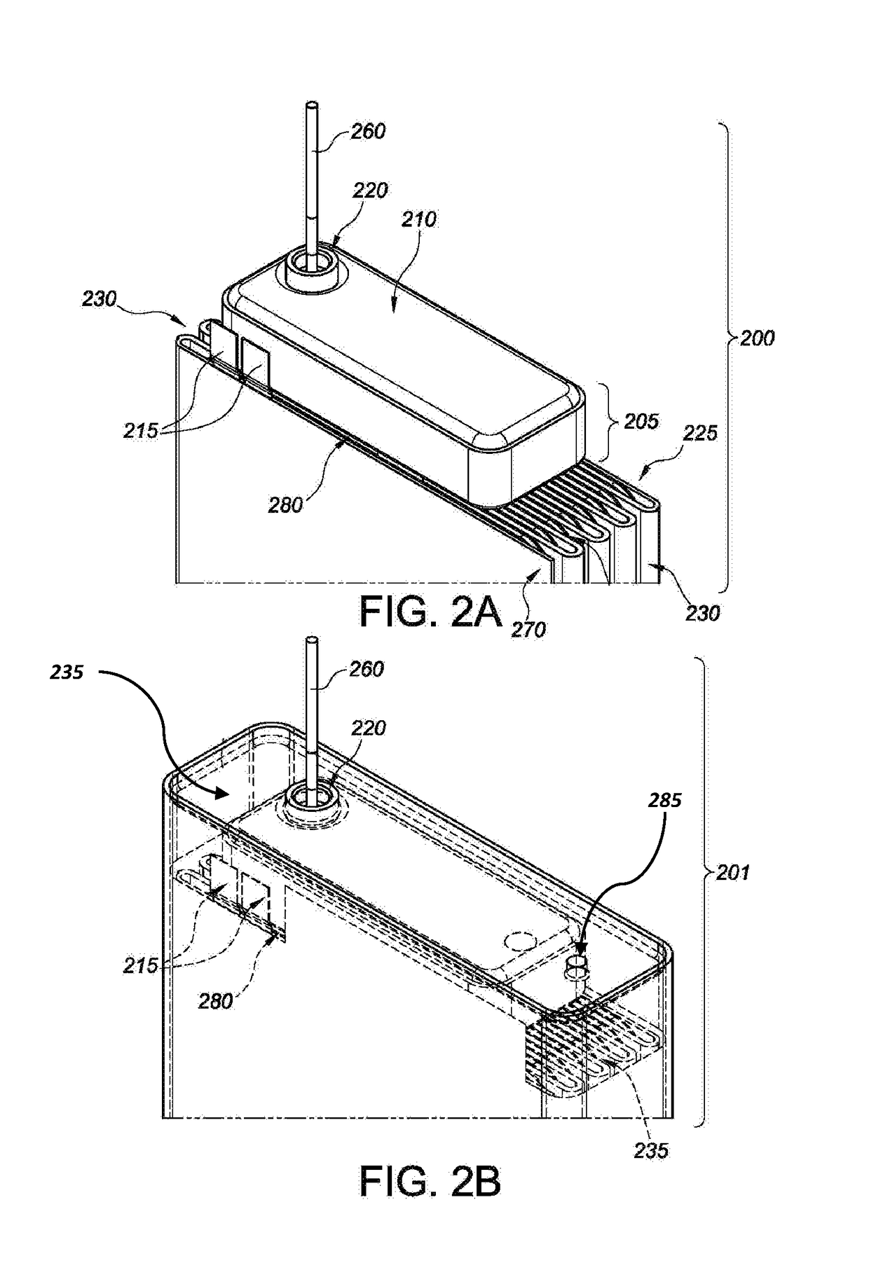
[0107]New insulator designs were tested to evaluate their ability to prevent lithium cluster shorts. Various experimental designs, and control cells, were built, which underwent testing pursuant to harsh “worst case” lithium cluster conditions. The new designs employ overlapping insulator compartments as discussed above, to prevent clusters from entering the insulation pocket, i.e., around the cathode bridge and pin. The new designs also create cluster cavities at either end of the cell, which are un-insulated portions of the case and lid that permit cluster growth in such non-critical areas of the cell.
[0108]Cells were tested per standard discharge parameters, where background is applied prior to the first pulse train, between each pulse train, and then after the final pulse train. The pulse current density was performed within standard protocol ranges. Discharge testing was performed in a “pin down” orientation, which is a 180° rotation in comparison to the electrochemical cells...
example 2
lts
[0109]Cells were discharge tested as outlined in a pin down orientation. The results are detailed below and with respect to Table 1. Typically, “slow” or erratic voltage recovery data indicates that a tested cell shorted during its respective test. Post-test microcal was performed in any event to confirm shorts. All cells showed rising voltage between EOT and start of DA between standard testing ranges except for certain cells that shorted during testing. The results are as follows.
TABLE 1Test Identifier (FIG.)Cell DesignResults (No. of Shorts)Design “C”Controls3 / 8Design / Test 2Embodiment 10 / 8Design / Test 3Embodiment 20 / 8
example 3
onal (DA) Results
[0110]Regarding this example, part of the electrochemical cell casing was removed or peeled back to expose side views of the lid area for controls and Embodiments 1-2, as noted above, after the testing was performed. In general, the clusters formed at the lid and in the cluster cavities at both ends of the cell (data not shown). Elevated views of the cell stack and first insulator member for all cells were also studied to ascertain the extent and location of the lithium cluster formation for both the controls and experimental designs, i.e., Embodiments 1-2. With respect to the control cells, cluster formation was observed inside the lid insulator for five cells (data not shown).
[0111]Concerning Embodiments 1 and 2 (Designs 2 and 3), however, essentially no cluster formation was observed in the insulator compartment other than nominal precipitation in two cells, where each had a single isolated cluster therein (data not shown). Design 3 cells did appear to have some ...
PUM
| Property | Measurement | Unit |
|---|---|---|
| current densities | aaaaa | aaaaa |
| current densities | aaaaa | aaaaa |
| size | aaaaa | aaaaa |
Abstract
Description
Claims
Application Information
 - R&D
- Intellectual Property
- Life Sciences
- Materials
- Tech Scout
- Unparalleled Data Quality
- Higher Quality Content
- 60% Fewer Hallucinations
Browse by: Latest US Patents, China's latest patents, Technical Efficacy Thesaurus, Application Domain, Technology Topic, Popular Technical Reports.
© 2025 PatSnap. All rights reserved.Legal|Privacy policy|Modern Slavery Act Transparency Statement|Sitemap|About US| Contact US: help@patsnap.com


