Installation method for setting up conveying devices

Active Publication Date: 2018-05-10
INTERROLL HLDG
View PDF10 Cites 1 Cited by
  • Summary
  • Abstract
  • Description
  • Claims
  • Application Information

AI Technical Summary

Benefits of technology

This invention describes a method for installing conveyor systems automatically, whether it is a new system or an existing system that has been modified. The method involves placing an object (like a package or carton) on the first conveyor segment and using a visual and / or acoustic user interface to display the status of the learning mode and show if there was an incorrect detection of direction of rotation. The conveyor system uses a control unit and light sources to produce visual signals or activates and deactivates the conveyor drive to produce acoustic signals. This allows users to easily monitor the learning mode and make any necessary adjustments. Overall, this method simplifies the installation process and improves the efficiency of conveyor systems.

Problems solved by technology

This results in complex conveying devices consisting of several conveyor segments.
This involves and consumes a significant amount of work and time, because it requires that many parameters be set in order to configure the control units.
Setting up complex conveying devices also requires skilled personnel.
Due to the complexity involved, the likelihood is nevertheless great that individual control units are incorrectly configured, which, in turn, may consume additional time and expense troubleshooting for defects.

Method used


Image

  • Installation method for setting up conveying devices
  • Installation method for setting up conveying devices
  • Installation method for setting up conveying devices

Examples


Embodiment Construction

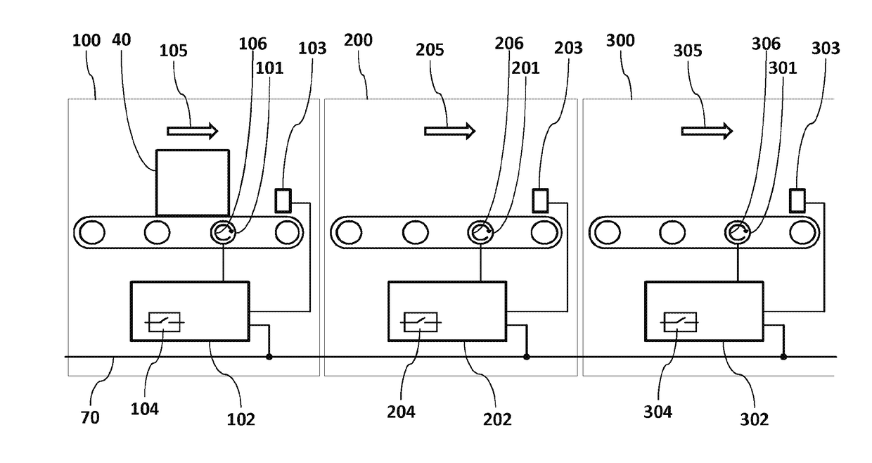
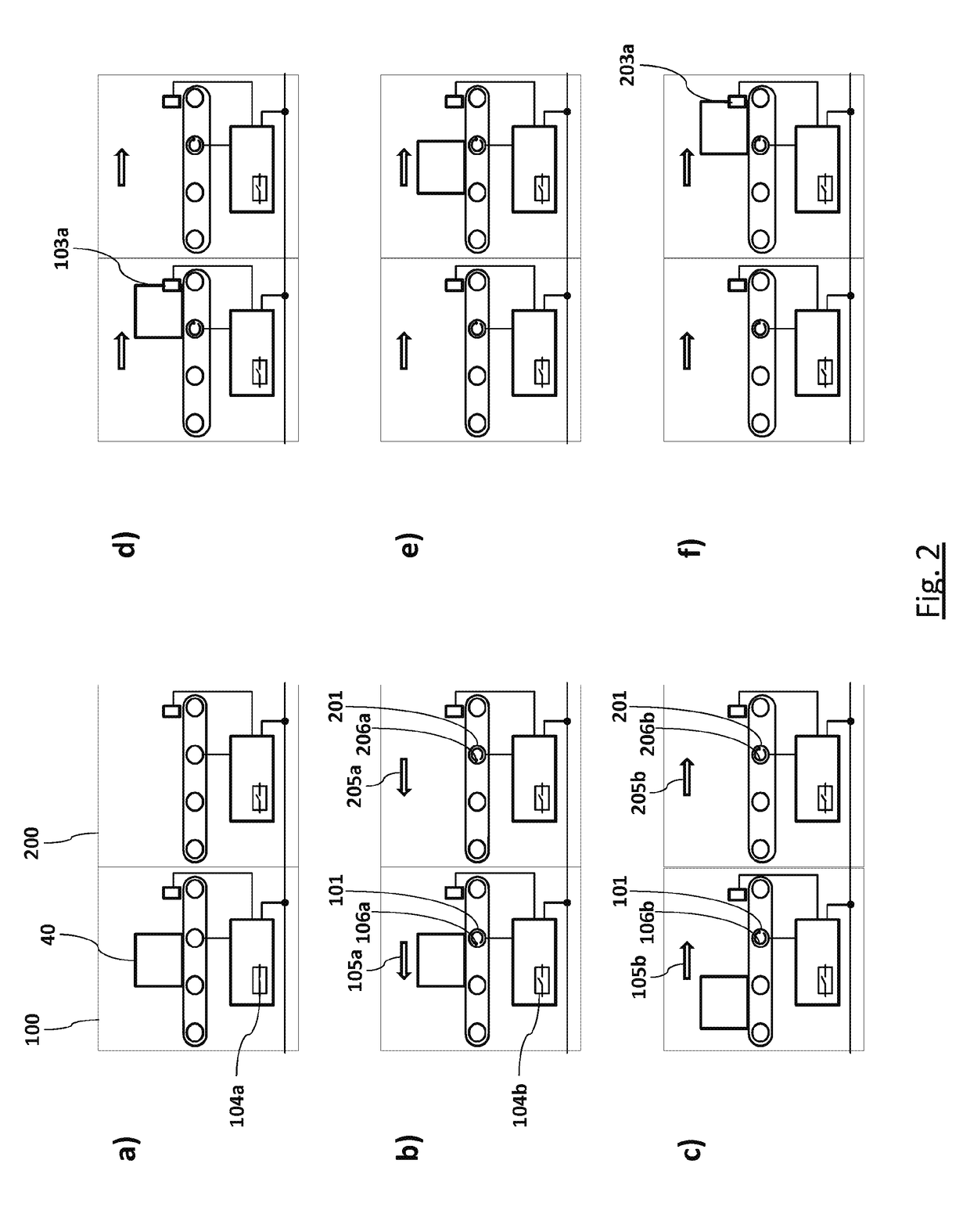
[0084]As referenced in the Figures, the same reference numerals may be used herein to refer to the same parameters and components or their similar modifications and alternatives. For purposes of description herein, the terms “upper,”“lower,”“right,”“left,”“rear,”“front,”“vertical,”“horizontal,” and derivatives thereof shall relate to the present disclosure as oriented in FIG. 1. However, it is to be understood that the present disclosure may assume various alternative orientations and step sequences, except where expressly specified to the contrary. It is also to be understood that the specific devices and processes illustrated in the attached drawings, and described in the following specification, are simply exemplary embodiments of the inventive concepts defined in the appended claims. Hence, specific dimensions and other physical characteristics relating to the embodiments disclosed herein are not to be considered as limiting, unless the claims expressly state otherwise. The draw...


PUM


Abstract

The invention relates to an installation method for setting up a control unit in a conveying device, wherein a first control unit controls an upstream first conveyor segment and a second control unit controls a downstream second conveyor segment. The method according to the invention comprises the steps of: placing an object on a first conveyor segment; activating a learning mode in a first and second control unit; activating a first and second conveyor drive by means of the respective first and second control unit; automatically conveying the object in the direction of the second conveyor segment; and storing an installation parameter in the second control unit depending on the triggering of the first or second sensor signal.

Description

CROSS-REFERENCE TO FOREIGN PRIORITY APPLICATION[0001]The present application claims the benefit under 35 U.S.C. § 119(b) of PCT / EP2016 / 058719, filed Apr. 20, 2016, which claims priority to German Application No. 102015106034.5, filed Apr. 20, 2015, entitled “Installation Method for Setting Up Conveying Devices.”FIELD OF THE INVENTION[0002]The invention relates to an installation method for setting up a control unit in a conveying device, wherein a first control unit controls an upstream first conveyor segment and a second control unit controls a downstream second conveyor segment. The first conveyor segment comprises a first conveyor drive for conveying an object through the first conveyor segment and a first sensor unit for detecting an object at a position within the first conveyor segment. The first conveyor drive and the first sensor unit are also in signal communication with the first control unit in order to control the first conveyor drive and to receive a first sensor signal...

Claims


Application Information

Patent Timeline
IPC IPC(8): B65G43/10
CPCB65G43/10B65G2203/0266G05B19/4189G05B19/4186G05B2219/25092G05B2219/25204B65G43/00G05B2219/23193G05B2219/2621G05B19/0426H04L61/5038
Inventor HENZE, HERBERT
Owner INTERROLL HLDG
Why Eureka
Try Eureka