
Programming of a flash memory cell

Active Publication Date: 2005-08-30
MONTEREY RES LLC
View PDF6 Cites 28 Cited by
  • Summary
  • Abstract
  • Description
  • Claims
  • Application Information

AI Technical Summary

Benefits of technology

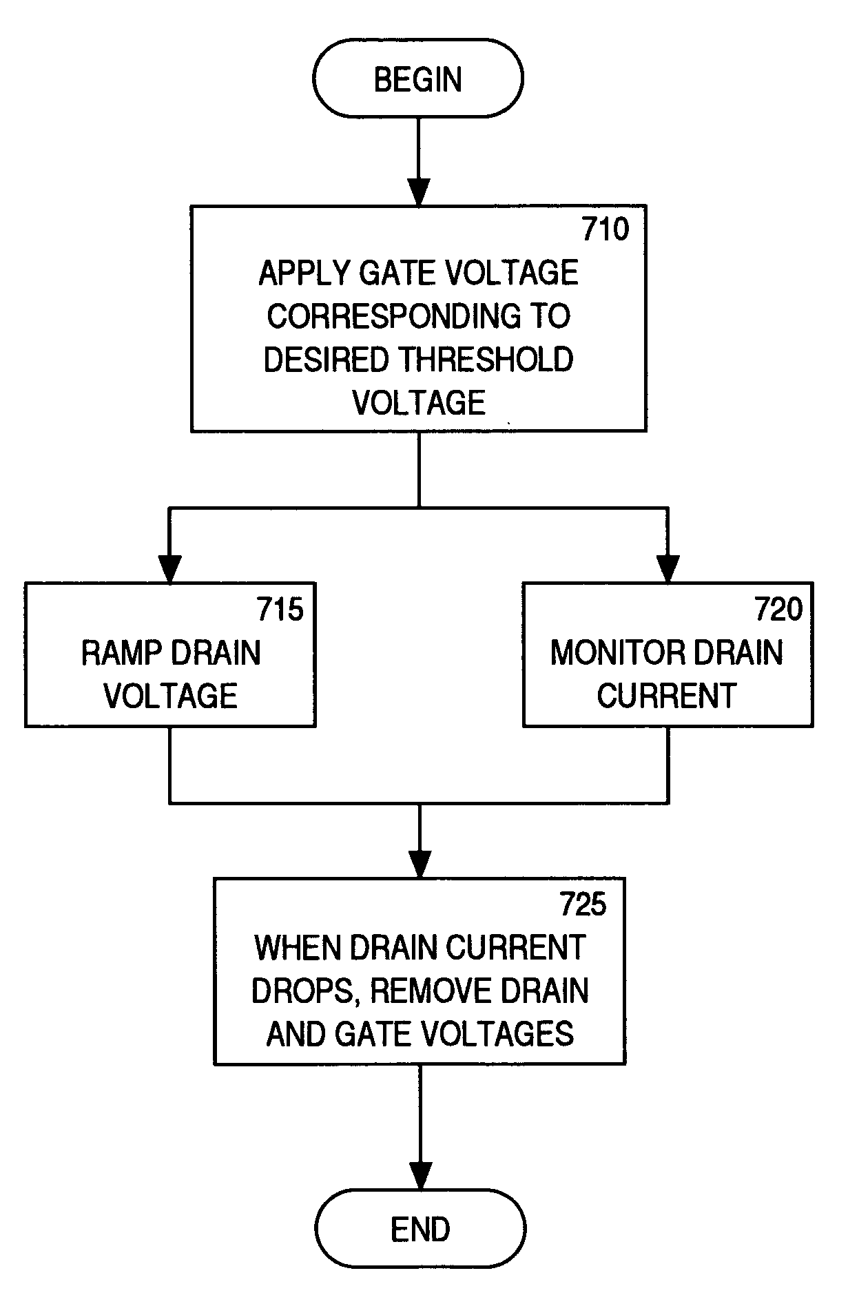
[0019]A novel method of programming a multiple level cell (MLC) is disclosed. In one embodiment, the method comprises applying a gate voltage having one of a plurality of levels, while applying a ramped drain voltage. Each of the plurality of gate voltage levels correspond to one of a plurality of threshold voltages. The plurality of threshold voltages are utilized to represent a plurality of bit combinations. The programming voltages applied to the gate and drain are removed when a drain current decreases. As a result, the present invention advantageously reduces the programming time while providing for programming of multiple threshold levels having relatively small distributions. The present invention is also advantageous in that reliability of the cell is increased, as compared to the convention art methods of programming.

Problems solved by technology

However, manufacturing process variations result in some cells programming faster than other cells.
As a result, the threshold cannot be set perfectly.
However, simply controlling the length of time that programming voltages are applied to the cell does not provide sufficient control of the distribution 305 of threshold values, to provide reliable operation of the memory device.
The multiple programming pulse method is disadvantageous in that the method results in a relatively long total programming time.
Furthermore, setup time between a programming pulse and a verify cycle and between the verify cycle and the next programming pulse is also incurred.

Method used


Image

  • Programming of a flash memory cell
  • Programming of a flash memory cell
  • Programming of a flash memory cell

Examples


Embodiment Construction

[0031]Reference will now be made in detail to the embodiments of the invention, examples of which are illustrated in the accompanying drawings. While the invention will be described in conjunction with the preferred embodiments, it will be understood that they are not intended to limit the invention to these embodiments. On the contrary, the invention is intended to cover alternatives, modifications and equivalents, which may be included within the spirit and scope of the invention as defined by the appended claims. Furthermore, in the following detailed description of the present invention, numerous specific details are set forth in order to provide a thorough understanding of the present invention. However, it will be obvious to one of ordinary skill in the art that the present invention may be practiced without these specific details. In other instances, well-known methods, procedures, components, and circuits have not been described in detail as not to unnecessarily obscure aspe...


PUM


Abstract

A method of programming a memory device comprises applying a first programming voltage to one of a plurality of wordlines, corresponding to a cell to be programmed. The first programming voltage is substantially equal to the desired threshold voltage. A second programming voltage is also applied to one of a plurality of bitlines, corresponding to the cell to be programmed. The second programming voltage gradually increases from a low level toward a high level. The first programming voltage and second programming voltage are removed when the corresponding bitline current begins to decrease.

Description

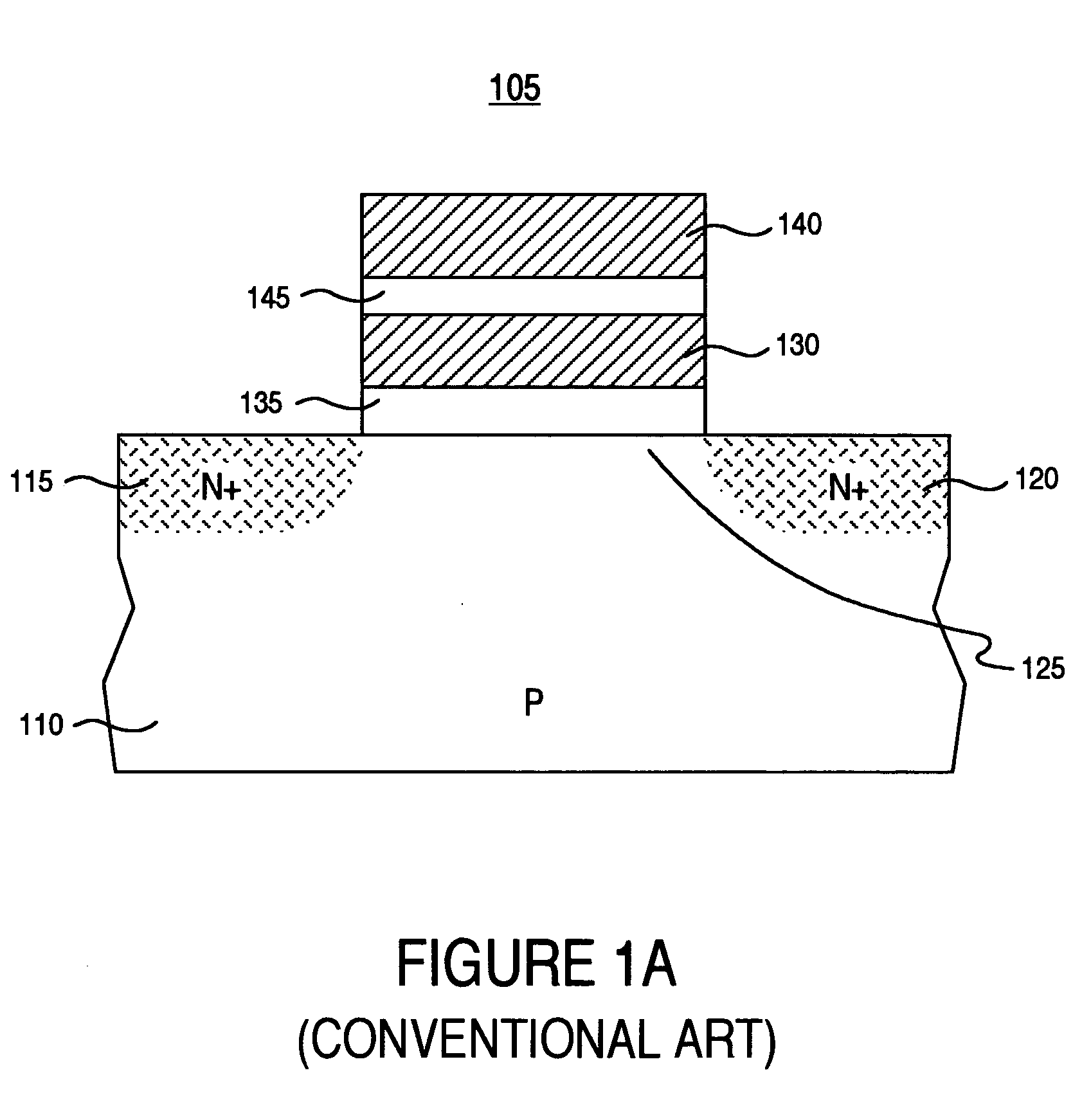
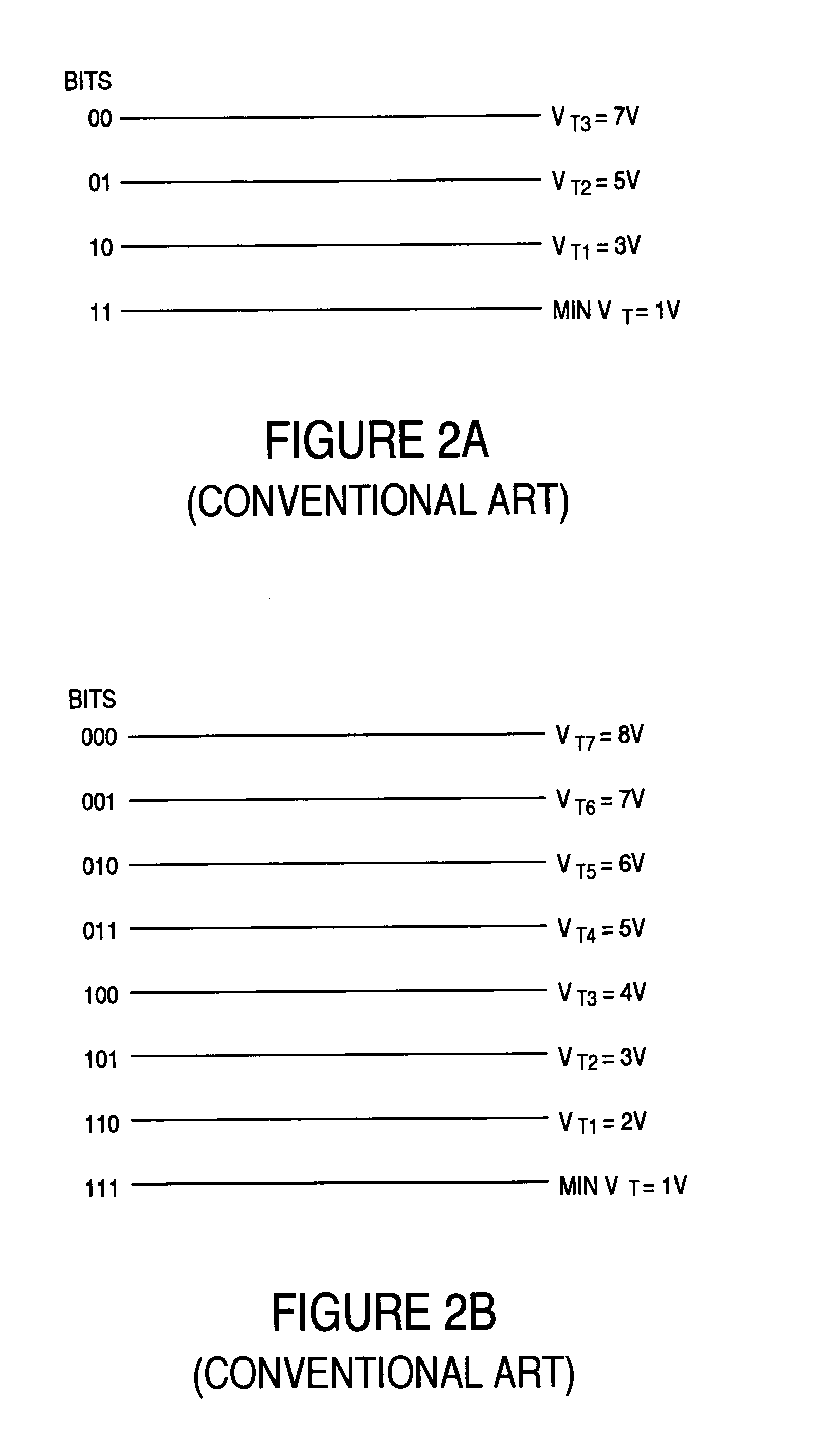
FIELD OF THE INVENTION[0001]Embodiments of the present invention relate to memory devices, and more particularly to programming a multiple level cell (MLC).BACKGROUND OF THE INVENTION[0002]As semiconductor memory technology progresses, increasing device density continues to be critical. Increasing device density may be achieved by scaling the memory cell. Alternatively, multiple bits can be store in each memory cell. For example, two bits can be stored in a multiple level cell MLC) utilizing four threshold levels. An un-programmed cell has a minimum threshold value determined by fabrication parameters (e.g., core implant doping level). The minimum threshold value is typically utilized to represent the two-bit combination of ‘11’; a first threshold value represents the combination ‘10’; a second threshold value represents the combination ‘01’; and a third threshold value represents the combination ‘00’. Similarly, three bits can be stored in a multiple level cell utilizing eight thre...

Claims


Application Information

Patent Timeline
IPC IPC(8): G11C16/04G11C11/56G11C16/34
CPCG11C11/5628G11C16/3454G11C16/3468
Inventor PARK, SHEUNG HEELEUNG, WING HANFASTOW, RICHARD M.
Owner MONTEREY RES LLC
Learn More