
Expansible Intersomatic Cage

a cage and lordosis technology, applied in the field of extending lordosis cages, can solve the problems of difficult observation of specific lordosis or control of lordosis obtained by surgeons, relatively invasive implantation for patients, and surgeons exerting excessive pressure on implants, etc., to achieve easy expansion and increase stability and reliability. , the effect of facilitating surgeons

Active Publication Date: 2018-05-03
LDR MEDICAL
View PDF97 Cites 27 Cited by
  • Summary
  • Abstract
  • Description
  • Claims
  • Application Information

AI Technical Summary

Benefits of technology

The invention proposes a better expandable intervertebral implant that is more stable, reliable, and easier for surgeons to use while observing the patient's lordosis. The implant has a flexible arm that can be expanded by sliding a proximal portion of it with respect to the body, which increases the space occupied by the implant. This makes it easier for the implant to expand and conform to the patient's needs.

Problems solved by technology

The implants of the prior art therefore generally have a very large volume allowing their implantation relatively invasive for the patient.
Nevertheless, this type of expansible cages includes a certain number of drawbacks.
In particular, during their expansion, the surgeon has to exert an excessive pressure on the implant, notably because its expansion is simultaneously accomplished on two axes orthogonal with each other.
Further, it is more difficult for the surgeon to observe a specific lordosis or to control the lordosis obtained.
Finally, this type of implant does not rest or only very little on the cortical bone of the vertebra, but on a softer portion of the bone at the centre of the intervertebral space, which reduces its stability and has a risk of sinking.
In addition, for some devices disclosed in the prior art, the expansion of this type of cages is limited.
This mechanism occupies a significant portion of the graft space, and prevents the insertion of many grafts, which is detrimental to good fusion of the vertebrae.

Method used


Image

  • Expansible Intersomatic Cage
  • Expansible Intersomatic Cage
  • Expansible Intersomatic Cage

Examples


Embodiment Construction

[0053]Many combinations of the features of diverse embodiments may be contemplated without departing from the scope of the application; one skilled in the art will select one depending on the economic, ergonomic or dimensional constraints or other considerations which may be observable or applicable to a given deployment.

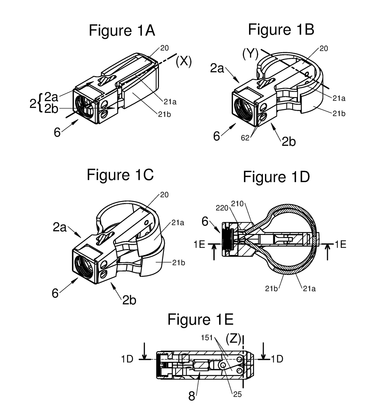
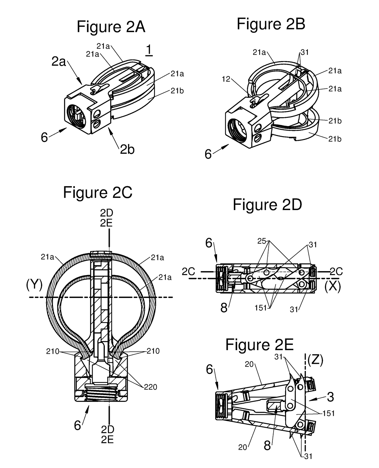
[0054]The sets of FIGS. 1A to 1E, 2A to 2E, 3A to 3D, 4A to 4D, 5A to 5D, 6A to 6C, and 7A to 7E depict various non-limiting embodiments of the present application. The various features of these embodiments may be mixed and combined in alternative more general embodiments, without any limitation. All of these embodiments include those not illustrated, and should be considered as fully within the scope of this disclosure. In addition, a person skilled in the art can possibly make use of the two other applications filed on the same day as the present application, by the same applicant, so as to ascertain possible functional and / or structural features which would be in...


PUM


Abstract

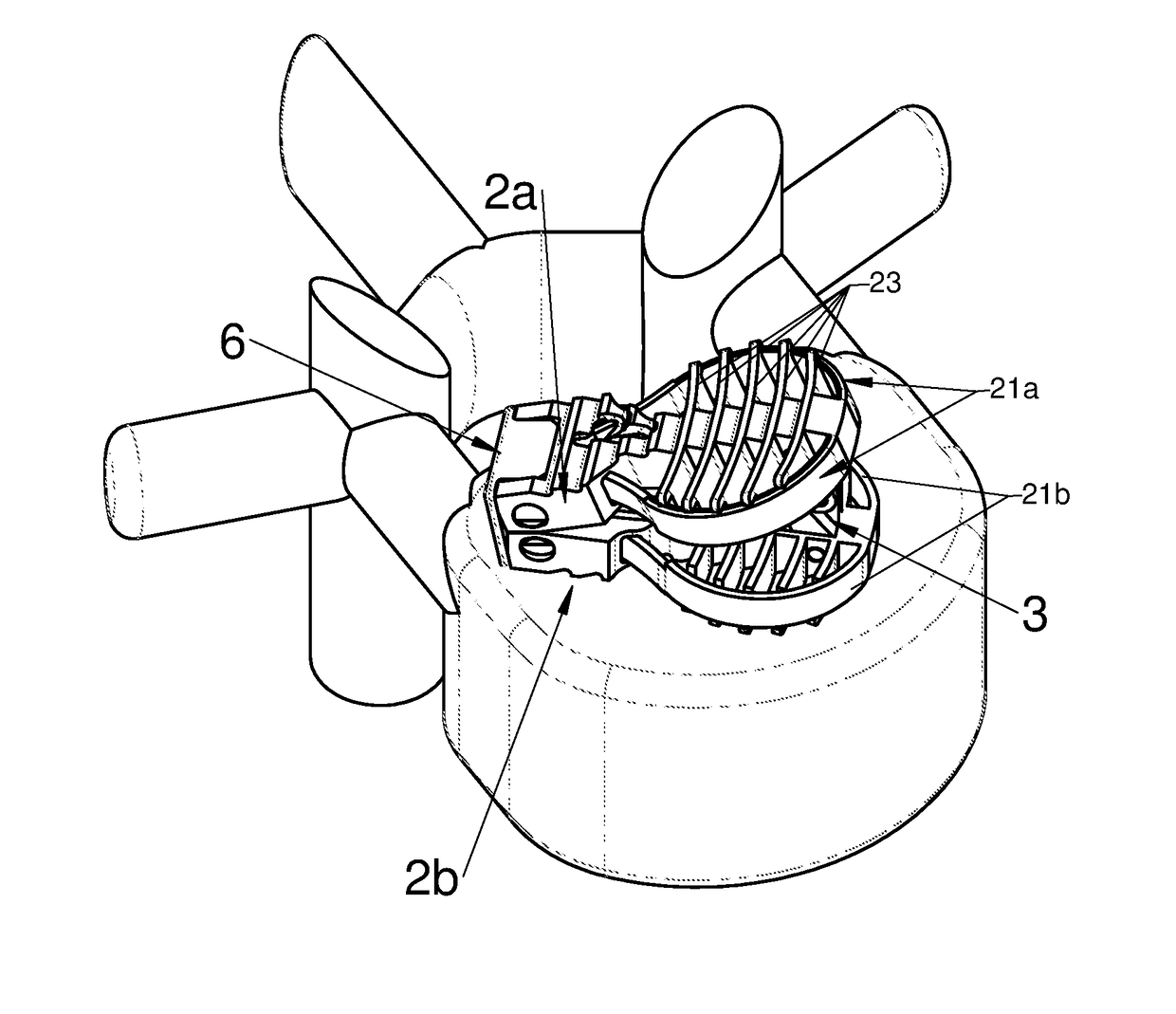
An expansible intervertebral implant is disclosed, various embodiments of which comprise an elongated body along a longitudinal axis comprised between a proximal end and a distal end, a flexible arm mounted in the vicinity of the distal end of the longitudinal body and movable between: a folded-back position with the arm substantially parallel to the axis, and a deployed position with the arm not parallel to the axis and away from the body to expand said implant along an axis, by assuming the general shape of a circular arc, a means for deployment of said flexible arm for deploying the latter from the folded-back position to the deployed position, by the sliding of a proximal portion of said flexible arm with respect to the body inducing an increase in the space occupied by the implant, greater than the space of the implant in the folded-back position.

Description

CROSS-REFERENCE TO RELATED APPLICATIONS[0001]This application claims priority under 35 U.S.C. § 119 to French Patent Application No. FR1660474 filed in FRANCE on Oct. 27, 2016, which is incorporated herein by reference.BACKGROUND[0002]The present application relates to the field of intervertebral cages and generally to the field of implants intended to be implanted between two adjacent verterbrae, to at least partly supplant an intervertebral disc to re-establish the height of the intervertebral space and the lordosis of the spinal segment, and more particularly to expansible vertebral implants of the intersomatic cage or corpectomy cage type.[0003]To remedy certain pathologies, sometimes it is sought to obtain fusion of at least two adjacent vertebrae, for example when at least one of their adjacent intervertebral discs is lesioned.[0004]From the prior art diverse arthrodesis techniques are known based on diverse types of implants, such as for example, intersomatic cages inserted i...

Claims


Application Information

Patent Timeline
IPC IPC(8): A61F2/44A61F2/30
CPCA61F2/442A61F2/4455A61F2/30767A61F2002/3006A61F2/4611A61F2002/30537A61F2002/30112A61F2002/30329A61F2002/30556
Inventor BERNARD, PIERRECHATAIGNER, HERVECHEBUHAR, CRAIGKIRGIS, ALEXANDERSHERBAN, ROSSLEQUETTE, SAMUELBOUGERE, EMMANUELFRESNEAU, AYMERICROCHE, NICOLAS
Owner LDR MEDICAL
Learn More