
Damage-resistant shower base and installation method

Inactive Publication Date: 2018-04-26
NOBLE CO LTD
View PDF5 Cites 14 Cited by
  • Summary
  • Abstract
  • Description
  • Claims
  • Application Information

AI Technical Summary

Benefits of technology

The patent aims to use the benefits of honeycomb without adding too much cost. It aims to use the honeycomb's ability to resist deformation and other beneficial properties.

Problems solved by technology

The location of a floor drain opening in retrofit installations can be particularly problematic since locations relative to adjacent walls vary widely.
One problem in particular is from compression and deformation issues to the upper surface of the base during installation.
The “compression and deformation issues” are caused in large part by depressions and irregularities in the shower floor, resulting in water pooling and poor water flow to the drain, which in turn results in customer complaints and building owner complaints about poor draining.
The compression and deformation issues to the base's upper surface can be caused by a variety of different mechanisms, including simple things like a plumber / installer placing a shoe or knee on the top surface during the installation (with the shoe or knee having sufficient weight or sharpness to cause a permanent depression that is reflected when tile is placed / installed at a later time on the upper surface), or by more difficult-to-manage items (such as damage or deformation during shipping, deformation during transport from the shipping container to the actual job site, or deformation occurring while the base is stored prior to installation, or damage or deformation while trying to fit a pre-manufactured base into a particular enclosed space to form the shower).

Method used


Image

  • Damage-resistant shower base and installation method
  • Damage-resistant shower base and installation method
  • Damage-resistant shower base and installation method

Examples


Embodiment Construction

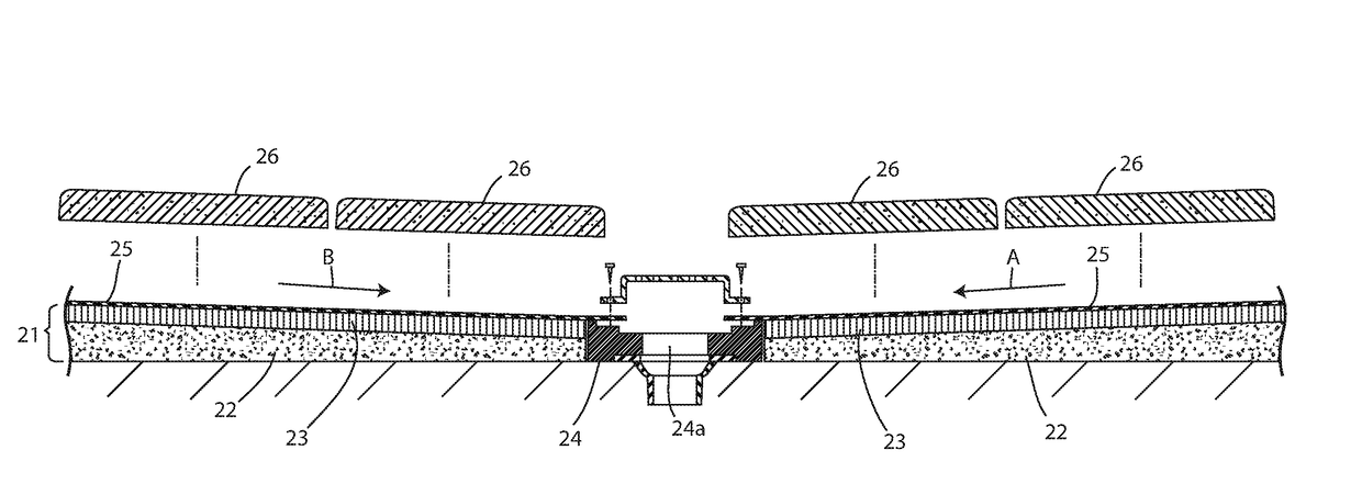
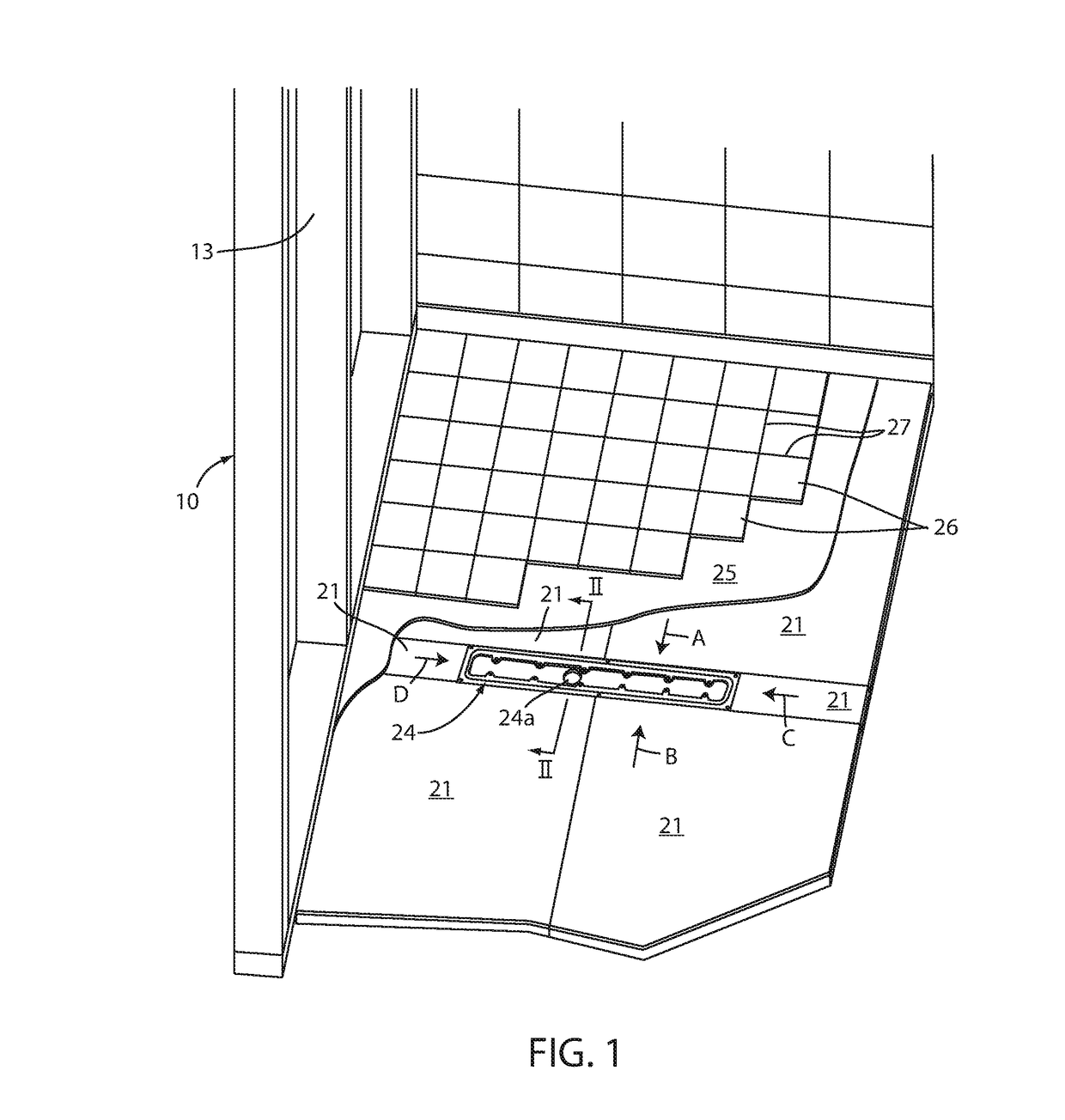
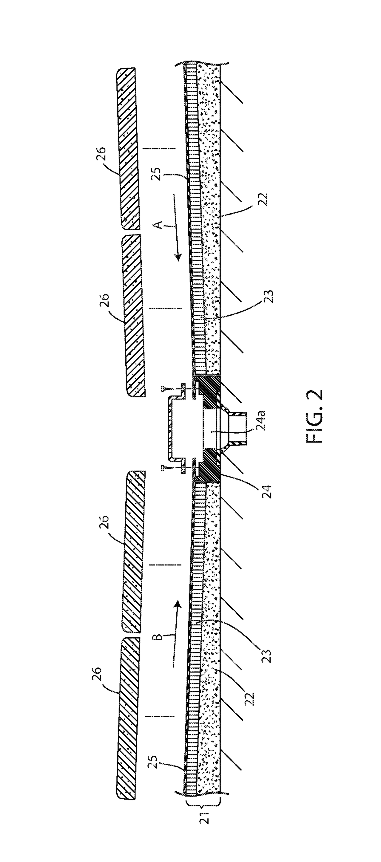
[0032]FIG. 1 is a perspective view of a partially-installed shower base apparatus in a shower structure 10 of a building. The shower structure 10 includes a floor surface, a first building wall (illustrated with drywall covering attached), and a second wall 13 (defined by the illustrated studs). The shower base apparatus is shown as partially installed in the shower structure 10. The shower base apparatus in FIG. 2 includes a combination slab 21, the combination slab 21 including at least one tapered or flat foam slab 22 (preferably polystyrene foam) with a sloped upper surface; and a deformation-resisting thin slab 23 (preferably a honeycomb slab of about 0.250-0.300 inch thickness) bonded to the sloped upper surface 22A of the foam slab 22 to form a deformation-resisting layer on the foam slab 22. The shower base apparatus 20 also includes a drain 24 (illustrated as a trench drain 24) with drain opening 24a, a waterproofing membrane 25, and tile 26 bonded using thinset to the wate...


PUM


Abstract

A shower base includes a combination slab where a foam slab (tapered or flat or multi-tapered) having a sloped upper surface is covered with a thin deformation-resisting honeycomb slab (e.g., 0.25-0.30 inch thickness, or more or less). A waterproof membrane and tile are installed on the shower base at the installation site. The method of installation includes installing the premanufactured combination slab at an installation site, and applying a waterproof membrane and thinset-bonded tile with gap-filling grout. This provides a high quality, flexible design that is both efficient and cost-competitive after installation. The honeycomb is sufficiently thick to overcome compression and deformation issues prevalent during tile installation.

Description

CROSS-REFERENCE TO RELATED APPLICATION[0001]This application claims the benefit under 35 U.S.C. § 119 (e) to U.S. Provisional Application Ser. No. 62 / 411,812, filed Oct. 24, 2016, entitled DAMAGE-RESISTANT SHOWER BASE AND INSTALLATION METHOD, the entire contents of which are incorporated herein.BACKGROUND[0002]The present invention relates to leak-proof water-draining shower bases and methods of installation, and more particularly relates to a shower base product including a foam slab with a sloped upper surface that is covered with damage-resisting slab (preferably honeycomb slab), and, at the installation site, also covered with a water-proof membrane and grouted tile. The present invention also includes a related method of installation and of manufacturing. It is contemplated that the present innovation is not limited to only shower bases, but instead can be used on many different collect-and-drain floors such as commercial kitchens and other wet areas.[0003]It is known to instal...

Claims


Application Information

Patent Timeline
IPC IPC(8): A47K3/40E03C1/12
CPCA47K3/40E03C1/12E03F5/0408
Inventor WADAGA, JAMES ANTHONY
Owner NOBLE CO LTD
Learn More