Heat treatment furnace charge frame circulation device
A technology of circulation equipment and heat treatment furnace, applied in the direction of heat treatment equipment, heat treatment furnace, furnace, etc., can solve the problems of inapplicable casting annealing treatment, complex production line structure, high cost of transformation and upgrading, etc., to achieve easy promotion, reduce labor costs, The effect of low upgrade cost
- Summary
- Abstract
- Description
- Claims
- Application Information
AI Technical Summary
Problems solved by technology
Method used
Image
Examples
Embodiment 1
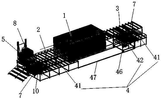
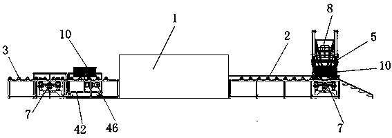
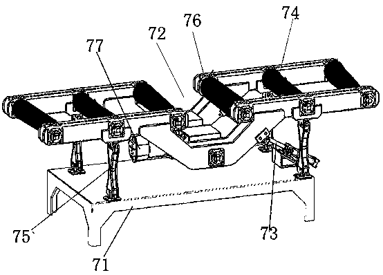
[0042] Such as Figure 1~2 As shown, a heat treatment charge frame circulation equipment includes an annealing furnace 1, a feed frame 2 connected to the feed system of the annealing furnace 1, a discharge frame 3 connected to the discharge system of the annealing furnace 1, and a connected feed frame 2 and the transfer frame 4 of the discharge frame 3, the feed frame turning mechanism 5 arranged on the feed frame 2 and the discharge frame turning mechanism 6 arranged on the discharge frame 3, the feed frame 2 and the output frame The feeding racks 3 are all conveying roller tables, which are arranged at both ends of the annealing furnace 1 respectively. The rail logistics vehicle 42 between the roads 41, a steering mechanism 7 is arranged between the feed rack 2 and the transfer rack 4, between the discharge rack 3 and the transfer rack 4, and the steering mechanism 7 has a lifting Functional roller mechanism, the feeding frame 8 is set on the feeding frame turning mechanism...
Embodiment 2
[0057] This embodiment is based on embodiment 1, and its technical scheme is basically the same as embodiment 1, the difference is:
[0058] Such as Figure 6~8 As shown, the feeding frame turning mechanism 5 includes a support, a slide rail, a chassis 51 for placing the feed frame 8 that is slidably connected with the slide rail, and the support includes a horizontal underframe 52 and a vertical frame that are fixedly connected to each other. The side frame 53, the slide rail includes a horizontal slide rail 54 arranged on the bottom frame 52 and a vertical slide rail 55 arranged on the side frame 53, and the bottom of the bottom frame 51 away from the side frame 53 is rotated with a horizontal The horizontal slide arm 56 that the slide rail 54 is adapted to, the chassis 51 is provided with a vertical slide arm near the end of the side frame 53, and the vertical slide arm includes a connecting arm 57 fixedly connected with the chassis 51 and a vertical slide rail 55 The slid...
Embodiment 3
[0062] This embodiment is based on embodiment 2, and its technical scheme is basically the same as embodiment 1, the difference is:
[0063] Such as Figure 9 and 10 Said, the fixed assembly includes a horizontal stopper 516 positioned on the upper part of the chassis 51 and a vertical fixing structure arranged on the chassis, the vertical fixing structure includes a fixed frame 517 fixed on the chassis 51, a fixed frame rotatably mounted on the fixed frame The turret 518 at the top of 517 and the cylinder 519 that drives the rotation of the turret 518, the turret 518 includes an inverted L-shaped clasp 520 for fixing the feed frame and a rotating shaft that is rotatably connected with the piston rod of the cylinder 519. The arm 521 and the bottom end of the cylinder body of the cylinder 519 are rotatably connected with the chassis 51 . When the piston rod of the cylinder 519 stretched out from the cylinder body, the piston rod pushed the rotating arm 521, and the clasp 520 ...
PUM
 Abstract
Description
Claims
Application Information
 - R&D
- Intellectual Property
- Life Sciences
- Materials
- Tech Scout
- Unparalleled Data Quality
- Higher Quality Content
- 60% Fewer Hallucinations
Browse by: Latest US Patents, China's latest patents, Technical Efficacy Thesaurus, Application Domain, Technology Topic, Popular Technical Reports.
© 2025 PatSnap. All rights reserved.Legal|Privacy policy|Modern Slavery Act Transparency Statement|Sitemap|About US| Contact US: help@patsnap.com


