
Vapor chamber and upper casing member thereof

a technology of vapor chamber and upper casing, which is applied in the field of vapor chamber, can solve the problems of difficult manufacture of conventional vapor chambers, and achieve the effects of improving the thermal conduction performance of vapor chambers, high thermal conductivity, and increasing the speed of thermal conduction

Inactive Publication Date: 2018-03-08
TAIWAN MICROLOOPS CORP
View PDF3 Cites 11 Cited by
  • Summary
  • Abstract
  • Description
  • Claims
  • Application Information

AI Technical Summary

Benefits of technology

The invention provides a vapor chamber that uses a support body to quickly conduct heat from the lower casing to each fin, which increases the speed of thermal conduction and improves the performance of the vapor chamber. The components of the vapor chamber, such as each support body, substrate, and fin, are made of the same material with high thermal conductivity, which ensures faster heat transfer.

Problems solved by technology

However, the thermal conduction performance, the manufacturing cost, and the level of difficulty of the manufacture of the conventional vapor chamber still have room for improvements.
Although such conventional vapor chamber has the thermal conduction performance, its practical application still has the following problems.

Method used


Image

  • Vapor chamber and upper casing member thereof
  • Vapor chamber and upper casing member thereof
  • Vapor chamber and upper casing member thereof

Examples


Embodiment Construction

[0015]The technical contents of this disclosure will become apparent with the detailed description of preferred embodiments accompanied with the illustration of related drawings as follows. It is intended that the embodiments and figures disclosed herein are to be considered illustrative rather than restrictive.

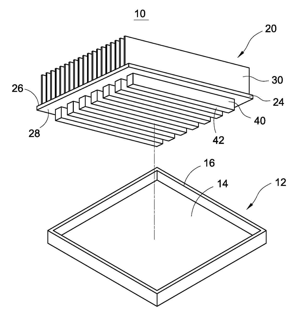
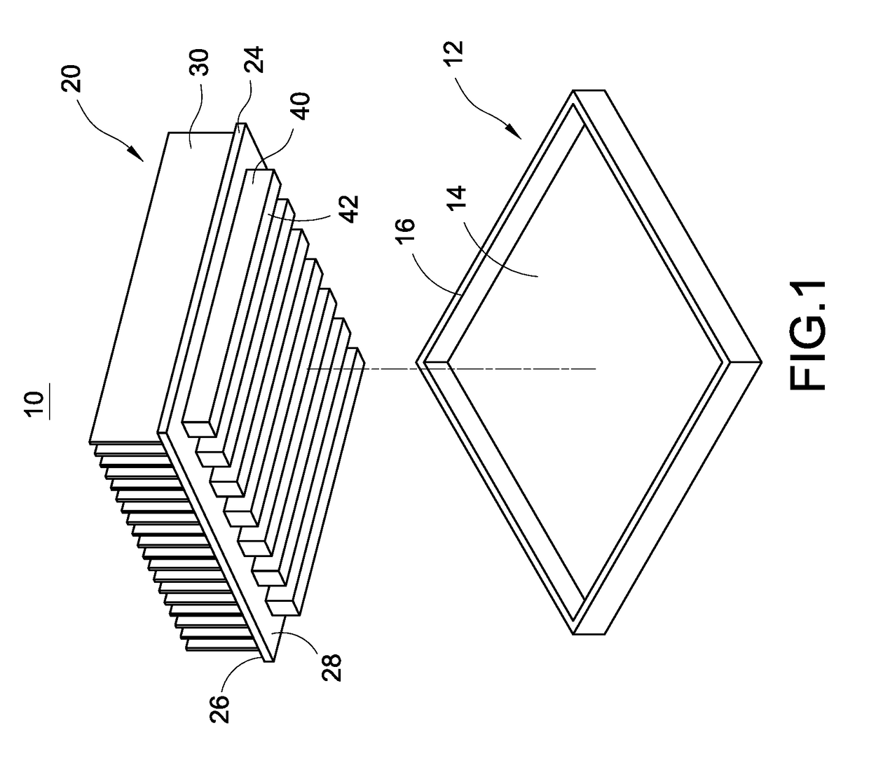
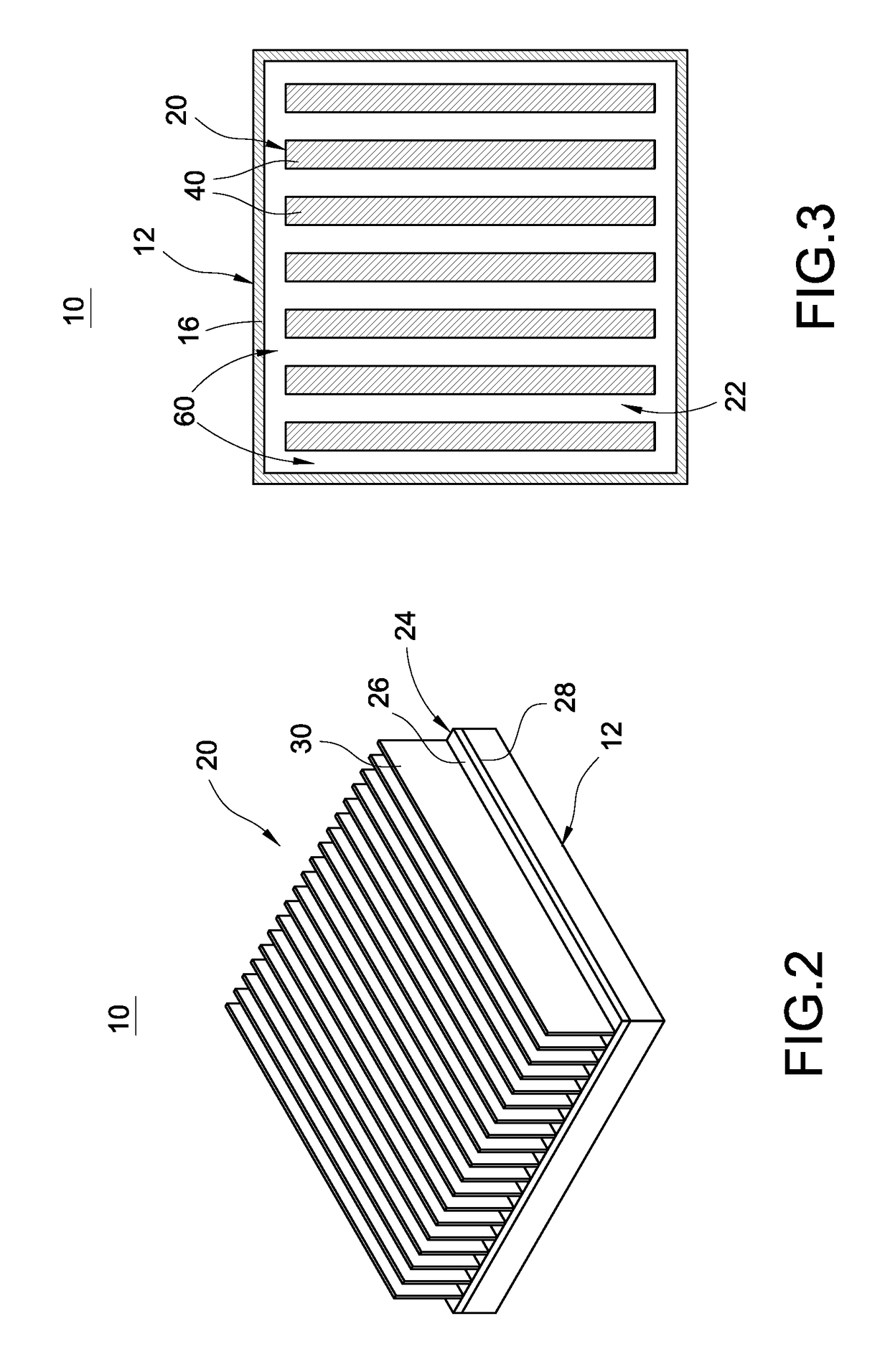
[0016]With reference to FIGS. 1 to 4 for a vapor chamber 10 of this disclosure, the vapor chamber 10 comprises a lower casing 12, an upper casing member 20 and a working fluid 50 (as shown in FIG. 4).

[0017]In this preferred embodiment, the lower casing 12 is made of copper, aluminum, copper-aluminum alloy, or any other material with good thermal conductivity. The lower casing 12 has a rectangular base plate 14, and a side plate 16 erected from the periphery of the base plate 14 separately. The rectangular base plate 14 is preferably contacted with a heat source (not shown in the figures), such as a chip or a processor for conducting the waste heat produced by the operation of...


PUM


Abstract

In a vapor chamber and its upper casing member, the vapor chamber includes a lower casing, an upper casing member and a working fluid. The upper casing member is engaged and sealed with the lower casing, and a chamber is enclosed between the upper casing member and the lower casing. The upper casing member includes a substrate, plural fins and plural support bodies which are integrally formed with one another. The substrate has an outer surface and an inner wall disposed opposite to each other, and each fin is formed and extended from the outer surface, and each support body is formed and extended from the inner wall. The working fluid is filled in the chamber. Each support body is provided for conducting heat from the lower casing to each fin.

Description

FIELD OF THE INVENTION[0001]The technical field generally relates to a vapor chamber, more particularly to a vapor chamber and an upper casing assembly applied to a heat source of electronic devices.BACKGROUND OF THE INVENTION[0002]As the computing speed of electronic devices increases, the heat generated by the electronic devices becomes increasingly higher. To overcome the large quantity of generated heat, manufacturers have introduced and extensively used a vapor chamber for dissipating the heat. However, the thermal conduction performance, the manufacturing cost, and the level of difficulty of the manufacture of the conventional vapor chamber still have room for improvements.[0003]In general, the conventional vapor chamber comprises an upper casing, a lower casing and a capillary tissue installed in the interior space between the upper casing and the lower casing, wherein the upper casing and the lower casing are welded and engaged with each other, and then a working fluid is fi...

Claims


Application Information

Patent Timeline
Patent Type & Authority Applications(United States)
IPC IPC(8): F28D15/04H05K7/20
CPCH05K7/20336F28D15/04F28F3/048F28D15/0233F28D15/046F28F1/28H01L23/427
Inventor LIN, CHUN-HUNG
Owner TAIWAN MICROLOOPS CORP
Learn More