Electric heating vacuum drying bin

A technology of vacuum drying and drying warehouse, which is applied in the direction of heating to dry solid materials, non-heating to dry solid materials, heating devices, etc. Drying efficiency, simple structure, and improved thermal conductivity

Inactive Publication Date: 2020-09-22
MENGZHOU YUANHONG DRYING EQUIP RES & DEV CO LTD
View PDF0 Cites 0 Cited by
  • Summary
  • Abstract
  • Description
  • Claims
  • Application Information

AI Technical Summary

Problems solved by technology

There are dozens or hundreds of heating beam tubes in the vacuum drying chamber. If a certain heating beam tube leaks due to wear and corrosion, the leaking position of the heating beam tube is not easy to check, and it is even more difficult to repair. The entire vacuum drying chamber is scrapped and cannot be used

Method used


Image

  • Electric heating vacuum drying bin
  • Electric heating vacuum drying bin
  • Electric heating vacuum drying bin

Examples


Embodiment 1

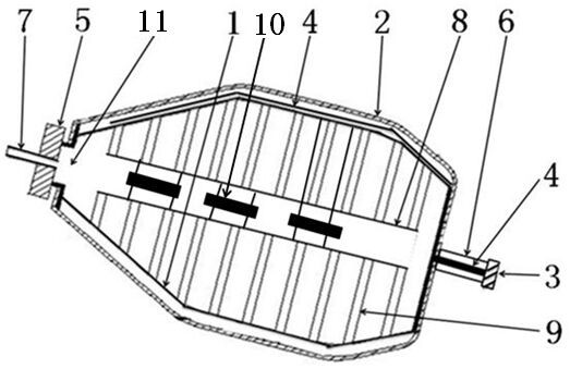
[0041] Such as figure 1 The electric heating vacuum drying chamber shown includes a drying chamber 1 , an insulating layer 2 , a sealing cover 5 and a conductive ring 3 .

[0042] The drying bin 1 is a single cone drying bin.

[0043] The drying chamber 1 includes a chamber body, an exhaust pipe 7 , an electric heating device, a transmission shaft 6 , a sealing cover 5 , a bracket 8 , and a power cord 4 .

[0044] The single-cone drying bin is a port 11.

[0045] The sealing cover 5 is installed on the port 11 of the drying bin 1 .

[0046] One end of the transmission shaft 6 is welded on the body of the drying chamber 1; the external driving device can drive the transmission shaft 6 to rotate, and the transmission shaft 6 rotates with the drying chamber 1 together.

[0047] The exhaust pipe 7 is installed on the sealing cover 5, and the inside of the exhaust pipe 7 is connected to the interior of the drying chamber 1. The air in the drying chamber 1 and the moisture genera...

Embodiment 2

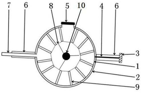
[0061] Such as figure 2 The electric heating vacuum drying chamber shown includes a drying chamber 1 , an insulating layer 2 , a sealing cover 5 and a conductive ring 3 .

[0062] The drying bin 1 is a double-cone drying bin.

[0063] The similarities between the combined structure of the electric heating vacuum drying chamber in Embodiment 2 and the electric heating vacuum drying chamber introduced in Embodiment 1 will not be repeated here.

[0064] Such as figure 2 The drying bin 1 of the electric heating vacuum drying bin shown includes a bin body, an exhaust pipe 7 , an electric heating device, a transmission shaft 6 , a sealing cover 5 , a bracket 8 , and a power cord 4 .

[0065] The exhaust pipe 7 is installed on the chamber body of the drying chamber 1, and the connection between the exhaust pipe 7 and the chamber body of the drying chamber 1 is fixed and sealed as a whole. The inside of the exhaust pipe 7 and the interior of the drying chamber 1 are In communicat...

Embodiment 3

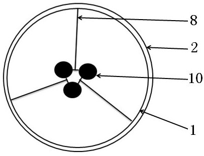
[0068] Such as figure 1 , image 3 The electric heating vacuum drying chamber shown includes a drying chamber 1 , an insulating layer 2 , a sealing cover 5 and a conductive ring 3 .

[0069] The drying bin is a drum drying bin, and the drum drying bin has two bin openings.

[0070] The combination structure of an electrically heated vacuum drying chamber in Embodiment 3 and the electric heating vacuum drying chamber introduced in Embodiment 1 will not be repeated here.

[0071] The electric heating device is a light wave tube 10, and the light wave tube 10 conducts heat conduction heating to the material through heat radiation.


PUM


Abstract

The invention discloses an electric heating vacuum drying bin. The electric heating vacuum drying bin comprises a drying bin, a heat insulating layer, a sealing cover and a conducting ring. The dryingbin comprises a bin body, an exhaust pipe, the sealing cover, electric heating devices, a transmission shaft and a bracket. Power of an external power source is transmitted to the electric heating devices through the conducting ring, the electric heating devices adjust the electric heating power according to the temperature needed in the material drying process, and the accurate temperature control of the electric heating devices can meet the temperature requirement of materials in the material drying processing process. Heat generated by the electric heating devices is directly conducted toheat the materials in the drying bin, the heat conducting speed is increased by 3-10 times, the efficiency of drying the materials in the drying bin is improved, and the purpose of rapidly drying thematerials is achieved. When one electric heating device is damaged and leaks, only the electric heating device does not work, and the use of the whole electric heating vacuum drying bin is not affected. The electric heating vacuum drying bin has a simple structure, and the heating temperature can be accurately controlled.

Description

technical field [0001] The invention relates to a vacuum drying chamber, in particular to an electrically heated vacuum drying chamber. Background technique [0002] Now the vacuum drying chamber of the vacuum dryer is composed of a drying chamber and a heating chamber. Heating and heat exchange is carried out by adding a high-temperature medium into the interlayer between the drying chamber and the heating chamber. The heat is in contact with the wet material through the chamber body of the drying chamber. , The heat dissipation area of ​​the drying bin body is small, and the heating area of ​​the material is small, which affects the heat conduction speed of the heat required for drying the material. [0003] At present, the vacuum drying chamber of some vacuum dryers uses heating beam tubes to increase the heat dissipation area, and the opening end of the heating beam tubes is fixedly welded on the chamber body of the drying chamber. In the same way, the high-temperature ...

Claims


Application Information

Patent Timeline
Patent Type & Authority Applications(China)
IPC IPC(8): F26B11/04F26B23/04F26B25/00F26B25/06F26B25/12F26B3/30F26B5/04
CPCF26B3/30F26B5/04F26B11/0445F26B23/04F26B25/00F26B25/001F26B25/06F26B25/12
Inventor 程长青江用文董春旺何星袁海波邓余良滑金杰
Owner MENGZHOU YUANHONG DRYING EQUIP RES & DEV CO LTD
Why Eureka
Try Eureka