
High-Precision Dispense System With Meniscus Control

Active Publication Date: 2018-02-15
TOKYO ELECTRON LTD
View PDF10 Cites 2 Cited by
  • Summary
  • Abstract
  • Description
  • Claims
  • Application Information

AI Technical Summary

Benefits of technology

This patent describes a system for dispensing a filtered liquid onto a substrate while compensating for slow filtration rates. This system reduces film defects such as gas bubbles, particle fall-on, organic residue, and metal impurities. It does this by minimizing exposure to gas and atmosphere and reducing parts used in the dispense line, which can cause defects. The system also minimizes flow eddies that can lead to chemical aggregation and provides precise dispense control. Overall, this technology improves the quality of the deposited films.

Problems solved by technology

One challenge, however, in being able to dispense various chemicals onto a wafer is avoiding defects in the dispensed chemicals.
Any small impurity or coagulation in the chemical can create defects on a wafer.
Such pre-filtered chemistry, however, can be very expensive and can develop defects in the chemistry during transport or use despite pre-filtering.
One complication with filtering immediately prior to dispensing (point of use filtering) is a reduction in flow rate.
A challenge with using such fine filters is that these filters decrease a rate of fluid flow of a given chemistry as the fluid chemistry is being pushed through these relatively fine filters.
Having a flow rate above or below such a given specified flow rate can result in defects on a substrate, insufficient coverage, and / or excessive coverage.
In other words, it is difficult to push a fluid through increasingly fine filters fast enough to meet dispense flow requirements.
Film defectivity can result from gas bubbles, fall-on particles, organic residue / polymer, metal impurities, coagulated particles, etc.

Method used


Image

  • High-Precision Dispense System With Meniscus Control
  • High-Precision Dispense System With Meniscus Control
  • High-Precision Dispense System With Meniscus Control

Examples


Embodiment Construction

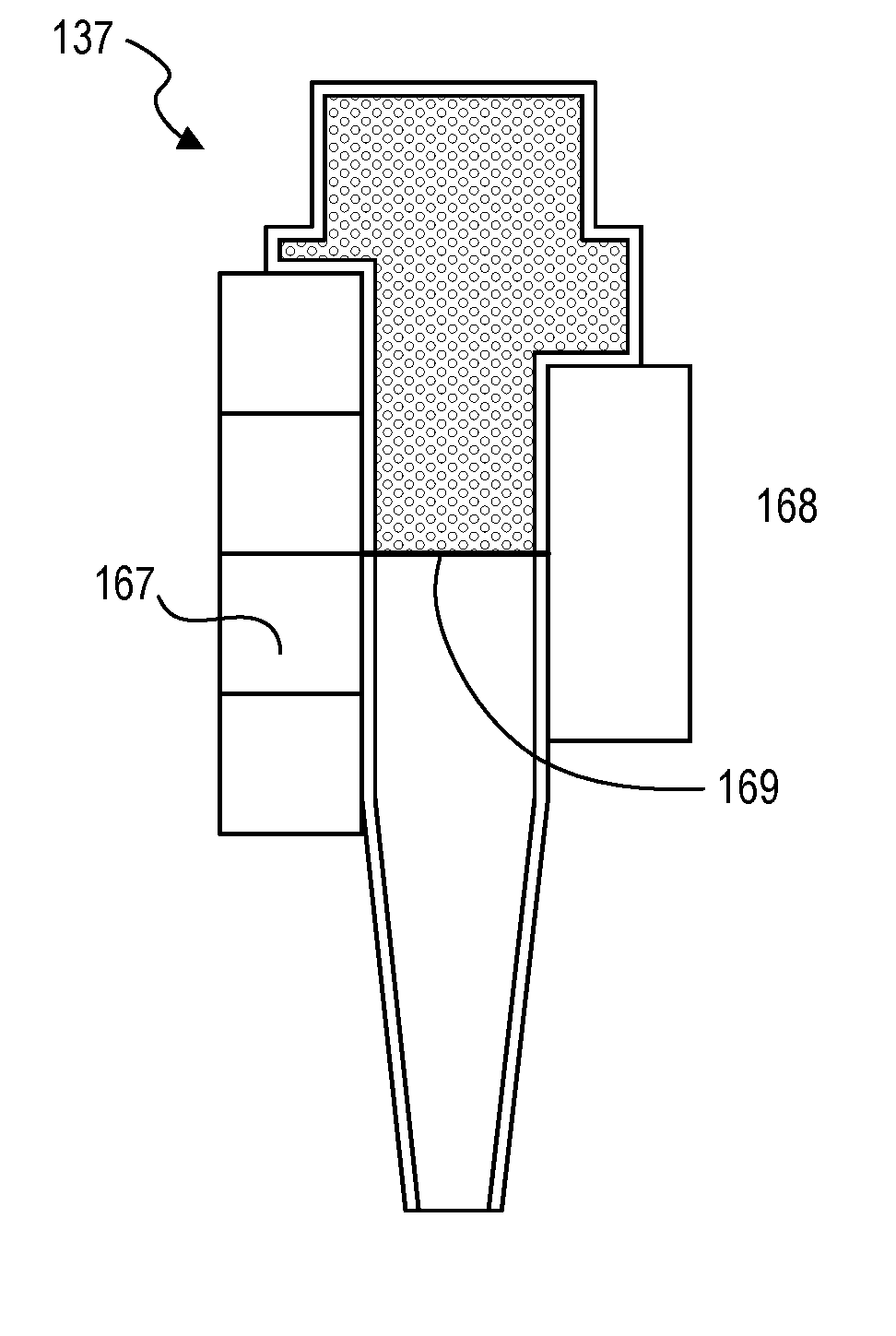
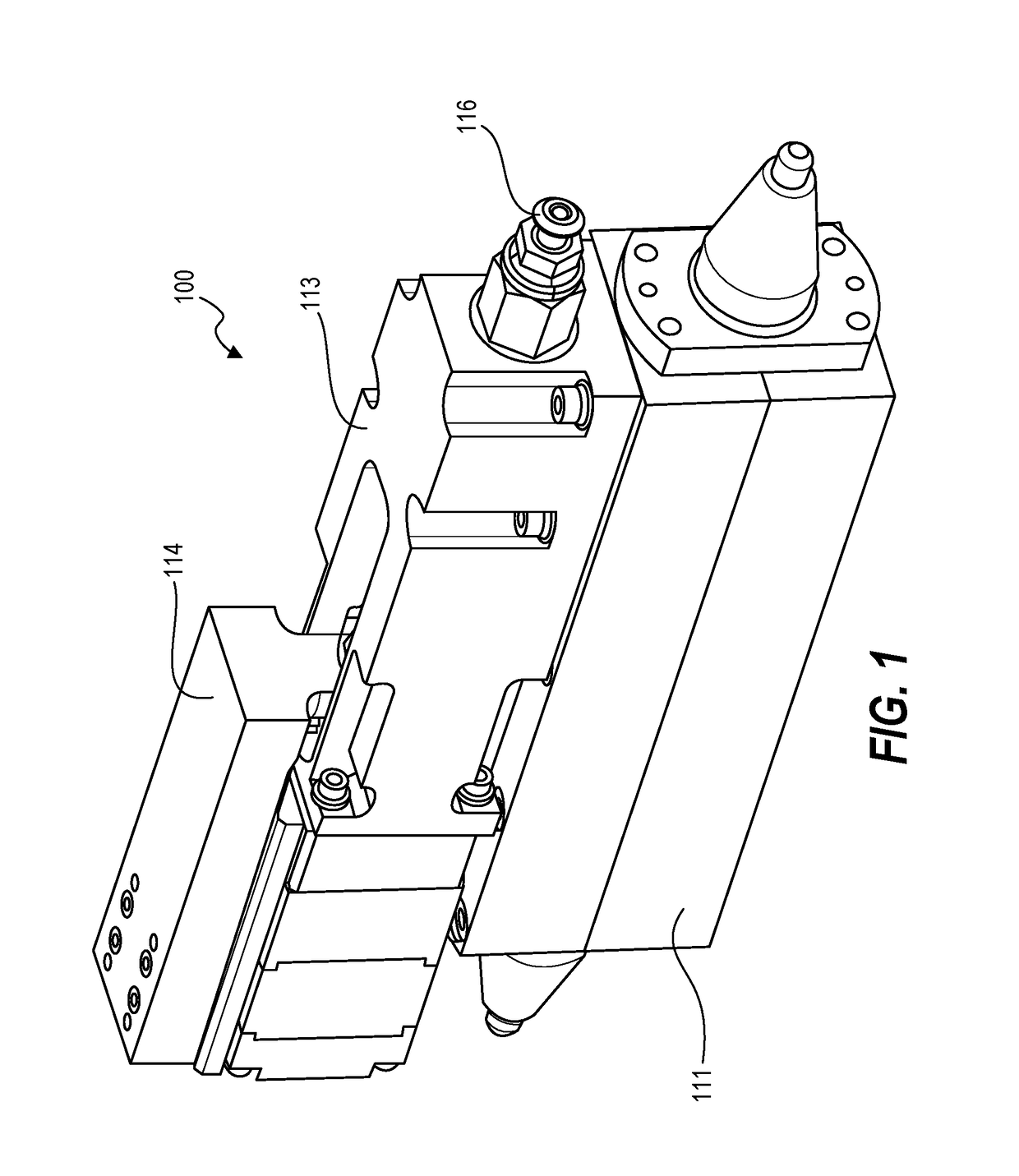
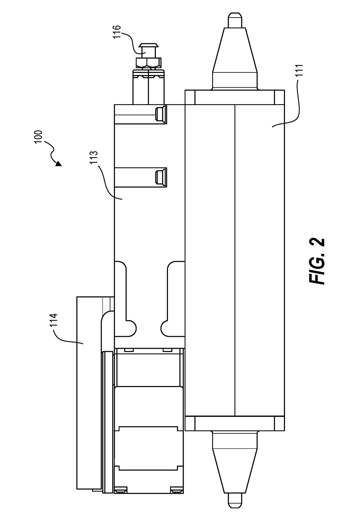
[0027]Techniques herein can be embodied as a bladder-based dispense system using an elongate bladder. This dispense system compensates for filter-lag, which often accompanies fluid filtering for microfabrication. This dispense system also provides a high-purity and high precision dispense unit. This dispense solution herein further reduces chances for defect creation. Conventional fluid delivery systems typically have a “dead leg” hanging off a fluid line. This dead leg can be a branch off the fluid line such as for a pressure measuring device or reservoir. Conventional fluid delivery systems can have other discontinuities that result in a significant chance of creating defects in the fluid, including various valves. Fluid connectors are designed to reduce imperfections on fluid conduit walls (inside walls). Any rough connectors or bends can cause places where fluid can recirculate, slow down, or otherwise get stopped which can cause coagulation. Thus, having a piston, baffle, or si...


PUM


Abstract

Techniques herein include a bladder-based dispense system using an elongate bladder configured to selectively expand and contract to assist with dispense actions. This dispense system compensates for filter-lag, which often accompanies fluid filtering for microfabrication. This dispense system also provides a high-purity and high precision dispense unit. A meniscus sensor monitors a position of a meniscus of process fluid at a nozzle. The elongate bladder unit is used to maintain a position of the meniscus at a particular location by selectively expanding or contracting the bladder, thereby moving or holding a meniscus position. Expansion of the elongate bladder is also used for a suck-back action after completing a dispense action.

Description

CROSS REFERENCE TO RELATED APPLICATIONS[0001]The present application claims the benefit of U.S. Provisional Patent Application No. 62 / 373,733, filed on Aug. 11, 2016, entitled “High-Precision Dispense System With Meniscus Control,” which is incorporated herein by reference in its entirety.BACKGROUND OF THE INVENTION[0002]This disclosure relates to semiconductor fabrication, and, in particular, to film dispensing / coating and developing processes and systems.[0003]Various microfabrication processes using coater / developer tools specify different chemicals to be dispensed onto a substrate (wafer) for particular designs. For example, various resist (photoresist) coatings can be dispensed onto a substrate surface. Resist coatings can vary by type of reaction to actinic radiation (positive / negative) and also by composition for different stages of patterning (front-end-of line, metallization, et cetera). Additionally, various developers and solvents may be selected to be dispensed onto a wa...

Claims


Application Information

Patent Timeline
IPC IPC(8): H01L21/027H01L21/02H01L21/66H01L21/67
CPCH01L21/0275H01L22/12H01L21/02118H01L21/67023B05B9/04B05B12/081B05B12/085G03F7/16H01L21/67017H01L21/6715H01L21/67253B05C5/02B05C11/1007B05C11/1047
Inventor DEVILLIERS, ANTON J.ROBISON, RODNEY L.NASMAN, RONALDTRAVIS, DAVIDGROOTEGOED, JAMESJACOBSON, JR., NORMAN A.HETZER, DAVIDHULI, LIORHOOGE, JOSHUA S.
Owner TOKYO ELECTRON LTD
Learn More