Therapy planning apparatus and particle radiation therapy apparatus
a technology of radiation therapy and treatment planning, applied in radiation therapy, x-ray/gamma-ray/particle-irradiation therapy, therapy, etc., to achieve the effect of high accuracy and short tim
- Summary
- Abstract
- Description
- Claims
- Application Information
AI Technical Summary
Benefits of technology
Problems solved by technology
Method used
Image
Examples
embodiment 1
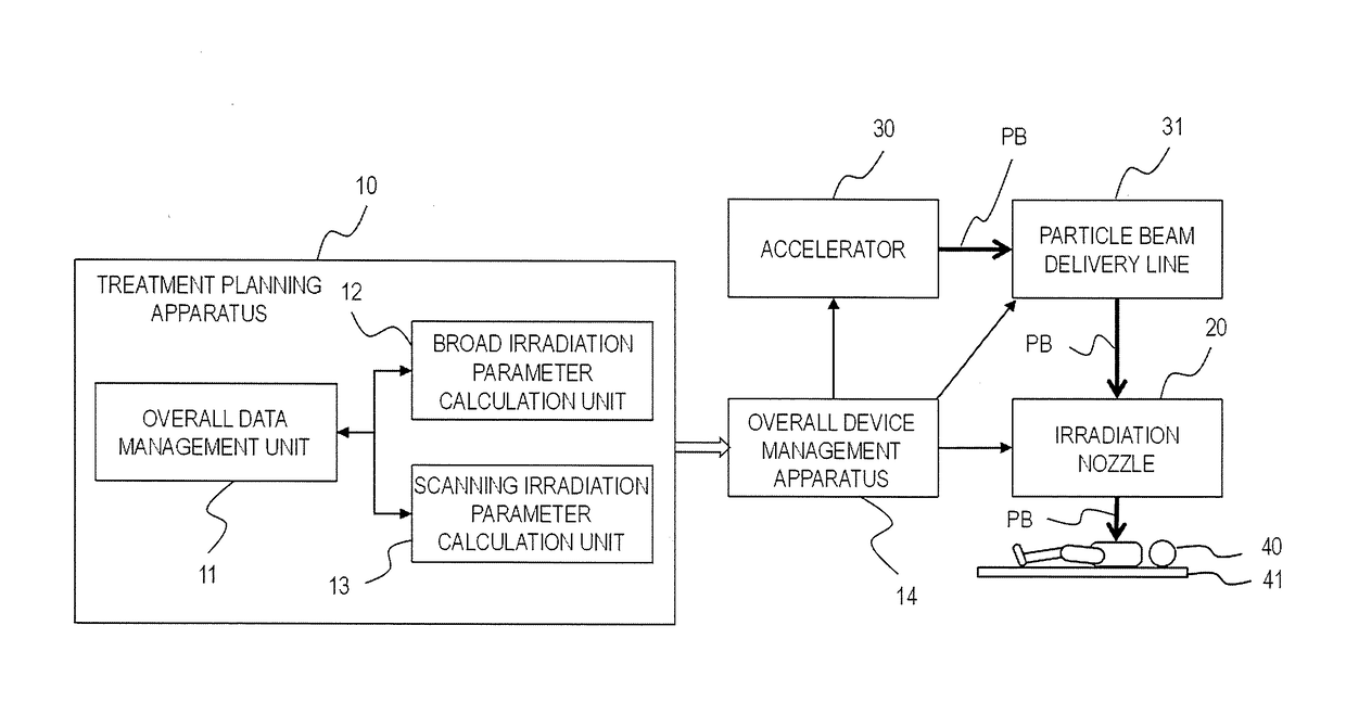
[0022]FIG. 1 is a block diagram showing an overall configuration of a particle beam therapy system including a treatment planning apparatus according to Embodiment 1 of the present invention. A particle beam PB extracted from an accelerator 30 is guided to an irradiation nozzle 20 through a particle beam delivery line 31. The irradiation nozzle 20 is provided with various parts and configured to switch between a broad irradiation and a scanning irradiation to irradiate with the particle beam PB a diseased site of a patient 40, an irradiation object. Meanwhile, a treatment plan how to irradiate the diseased site with the particle beam is in advance formulated appropriately to the diseased site of the patient by a treatment planning apparatus 10. The treatment planning apparatus 10 determines and stored therein operational parameters for respective devices, such as the accelerator 30, the particle beam delivery lines 31, and the irradiation nozzle 20, of the particle beam therapy syst...
embodiment 2
[0046]In Embodiment 1, no bolus is used in the broad irradiation. A bolus is usually fabricated for the range of the particle beam to conform to the shape of a diseased site, i.e., fabricated to adjust the energy distribution of the particle beam to the range conforming to a lower portion shape (distal shape) of a diseased site. A broad irradiation using a bolus allows for forming an irradiation dose distribution in conformity to a distal shape of a diseased site. However, irradiation from one direction is difficult to form an irradiation dose distribution in conformity to both distal and proximal shapes of a diseased site, i.e., the shape of the entire diseased site. Hence, a target irradiation dose distribution has been formed in the entire diseased site by a so-called multi-port irradiation such that irradiations are performed from, for example, an upper direction using a bolus for the distal shape and from the lower direction using a bolus for the proximal shape.
[0047]In Embodim...
embodiment 3
[0049]In Embodiment 2, the broad irradiation is performed using a bolus conforming to a distal shape of a portion of a diseased site. Conventionally, a bolus has been fabricated, each time on a patient-by-patient basis, as a patient-specific bolus conforming to the diseased site of a patient. Embodiment 3 is characterized in that the broad irradiation is performed not using a patient-specific bolus but using a bolus that is selected to approximate to a distal shape of a diseased site among a plurality of device-specific different shape boluses prepared beforehand. The plurality of different shaped boluses is referred here to as versatile boluses.
[0050]FIG. 8 shows a schematic illustration of irradiation performed according to Embodiment 3 using a versatile bolus. For example, one versatile bolus 441 to be mounted to the irradiation nozzle for use in the broad irradiation is selected among N versatile boluses stored in a versatile bolus box 440. In a case of using one versatile bolus...
PUM
 Abstract
Description
Claims
Application Information
 - R&D Engineer
- R&D Manager
- IP Professional
- Industry Leading Data Capabilities
- Powerful AI technology
- Patent DNA Extraction
Browse by: Latest US Patents, China's latest patents, Technical Efficacy Thesaurus, Application Domain, Technology Topic, Popular Technical Reports.
© 2024 PatSnap. All rights reserved.Legal|Privacy policy|Modern Slavery Act Transparency Statement|Sitemap|About US| Contact US: help@patsnap.com


