Dimpled Naccelle Inner Surface for Heat Transfer Improvement

Inactive Publication Date: 2017-11-02
GENERAL ELECTRIC CO
View PDF14 Cites 4 Cited by
  • Summary
  • Abstract
  • Description
  • Claims
  • Application Information

AI Technical Summary

Benefits of technology

The present invention provides a method for heating the engine nacelle of an aircraft. The method involves introducing a fluid into the engine nacelle and causing it to flow across pits defined by the nacelle. The fluid is then increased in turbulence as it flows across the pits. This method improves engine speed and efficiency.

Problems solved by technology

The accretion or buildup of ice on an aircraft engine is undesirable.
One problem with these methods is that distributing thermal energy evenly throughout the part to be heated is difficult.
As a result, either ice buildup happens on portions of the component that are not heated sufficiently or additional fluid flow from another part of the engine is needed to provide the required thermal load.
Such an increase in fluid flow reduces efficiency of the engine.

Method used


Image

  • Dimpled Naccelle Inner Surface for Heat Transfer Improvement
  • Dimpled Naccelle Inner Surface for Heat Transfer Improvement
  • Dimpled Naccelle Inner Surface for Heat Transfer Improvement

Examples


Embodiment Construction

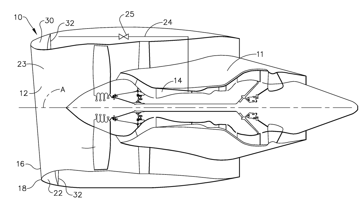
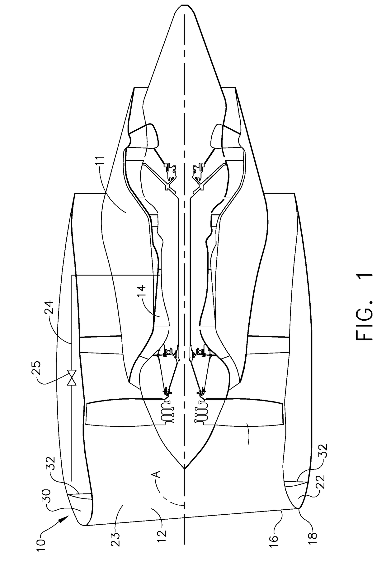
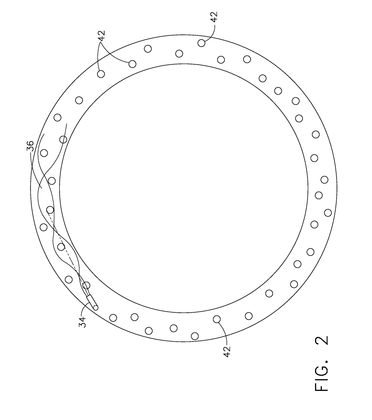
[0013]Referring to the drawings wherein identical reference numerals denote the same elements throughout the various views, FIG. 1 shows a partially cutaway view of a nacelle 10 that defines the leading portion of an engine 11. The nacelle 10 has a D-duct 30 defined therein that is configured with a plurality of dimples 42 as shown in FIG. 2. The dimples 42 are configured to increase the turbulence of fluid within the D-duct 30 and thus improve heat transfer from the fluid into and through the nacelle 10.

[0014]The nacelle 10 of the engine 11 has a wall 16 that has an inner surface 22 and an outer surface 23. The outer surface 23 of the wall 16 defines an inner lip 12 and an outer lip 18. The inner surface 22 defines the D-duct 30 in conjunction with a D-duct-floor 32.

[0015]The D-duct 30 is an annular chamber defined by the inner surface 22 of the wall 16 that is positioned around an axis A of the engine 11. As shown, the D-duct 30 has a D-shaped cross-section. As shown in FIG. 2, a ...


PUM


Abstract

An apparatus for improving heat transfer through a leading portion of an aircraft engine. The apparatus includes a wall that is defined by the leading portion. A surface is defined by the wall and the surface defines a channel through the leading portion of the aircraft engine. A source for a fluid that is fluidly connected to the channel. Pits are defined in the surface of the channel such that the bleed air can flow across the pits.

Description

BACKGROUND OF THE INVENTION[0001]The present invention relates to heating components of an aircraft engine and more particularly to heating the leading nacelle of an aircraft engine.[0002]The accretion or buildup of ice on an aircraft engine is undesirable. In order to reduce ice buildup, it is known to introduce hot fluids from one part of an engine to the other components of the engine. One problem with these methods is that distributing thermal energy evenly throughout the part to be heated is difficult. As a result, either ice buildup happens on portions of the component that are not heated sufficiently or additional fluid flow from another part of the engine is needed to provide the required thermal load. Such an increase in fluid flow reduces efficiency of the engine. Accordingly, there is a need for an apparatus to more efficiently use fluid flow to heat an aircraft component.BRIEF DESCRIPTION OF THE INVENTION[0003]This need is addressed by a structure within the component to...

Claims


Application Information

Patent Timeline
IPC IPC(8): F01D25/10F01D25/14F02C9/18
CPCF01D25/10F05D2220/32F02C9/18F01D25/14F02C7/047B64D15/04B64D2033/0233B64D33/02B64D2033/0286
Inventor TIWARI, PRASHANT
Owner GENERAL ELECTRIC CO
Why Eureka
Try Eureka