
Shape reconstruction using electronic light diffusing layers (e-glass)

a technology of electronic light diffusing layers and shape reconstruction, applied in the field of silhouette extraction and shape reconstruction of physical objects, can solve the problems of difficult 3d reconstruction of a specular object, difficult reflection by the object, and open problem of 3d reconstruction of an object with a specular surface (or non-lambertian surface), and achieve the effect of accurate silhouette extraction

Active Publication Date: 2017-10-19
CANON KK
View PDF2 Cites 12 Cited by
  • Summary
  • Abstract
  • Description
  • Claims
  • Application Information

AI Technical Summary

Benefits of technology

The patent describes a new method for extracting silhouettes from images, which can be used to create a visual hull of an object. This method involves using layers that control the amount of light that passes through them, resulting in a unique display pattern that can be used to extract the silhouette of the object. This method is advantageous because it can address pattern ambiguities and is more accurate compared to other techniques. Additionally, by controlling the transparency of the layers, a single captured image can often be enough for silhouette extraction. Furthermore, the method can estimate the depth of the surface of the object by using the extracted silhouette as a filter. Overall, this patent presents a new and improved way to extract silhouettes and reconstruct the actual shape of objects.

Problems solved by technology

3D reconstruction of a specular object remains a challenging task.
While there are several techniques capable of accurate reconstruction of objects with a diffuse (also called Lambertian) surface, the 3D reconstruction of an object with a specular (or non-Lambertian) surface is still an open problem.
One challenge is due to the fact that the appearance of a specular object, or a highly glossy object, depends on the viewpoint and on the surrounding environment.
In addition, for specular and highly glossy objects, reflection by the object may be quite complicated, and in general may involve multiple reflections by the object itself, in the path of reflection from a light source to image capture.
Thus, the multiple reflections destabilize and otherwise invalidate calculations based on ray tracing or triangulation, at least to the extent that such calculations rely on the assumption of only a single reflection at the surface of the object.
One of the main problem challenges for silhouette extraction is being able to have the texture of the foreground object different from the background pattern.
Diffuse objects can have any type of texture and in some areas it can match the background pattern; similar problem can also happen when objects are transparent (camera rays can be deflected to a similar background pattern) or have a specular surface that reflects the surrounding environment.
However, this simple triangulation fails when the object has concave areas and light rays are reflected more than once by the object's surface before reaching the camera.
A further issue arises in the context of specular objects, for which those of ordinary skill might also conclude that only a small part of the specular object can be reconstructed at each re-positioning of the object.
Thus, pixels that do not “see” the reflections of the screens are wasted since they provide little or no information.
It is further observed that even with an accurate reconstruction of the visual hull, it is still difficult to reconstruct the actual shape of the object since concave areas cannot be reconstructed from a visual hull alone.
However, this simple triangulation fails when the object has concave areas and light rays are reflected more than once by the object's surface before reaching the camera.
A further issue arises in the context of specular objects, for which those of ordinary skill might also conclude that only a small part of the specular object can be reconstructed at each re-positioning of the object.
Thus, pixels that are not reflected onto the screens are wasted since they provide little or no information.
It is further observed that even with an accurate reconstruction of the visual hull, it is still difficult to reconstruct the actual shape of the object since concave areas cannot be reconstructed from a visual hull alone.

Method used


Image

  • Shape reconstruction using electronic light diffusing layers (e-glass)
  • Shape reconstruction using electronic light diffusing layers (e-glass)
  • Shape reconstruction using electronic light diffusing layers (e-glass)

Examples


case 1

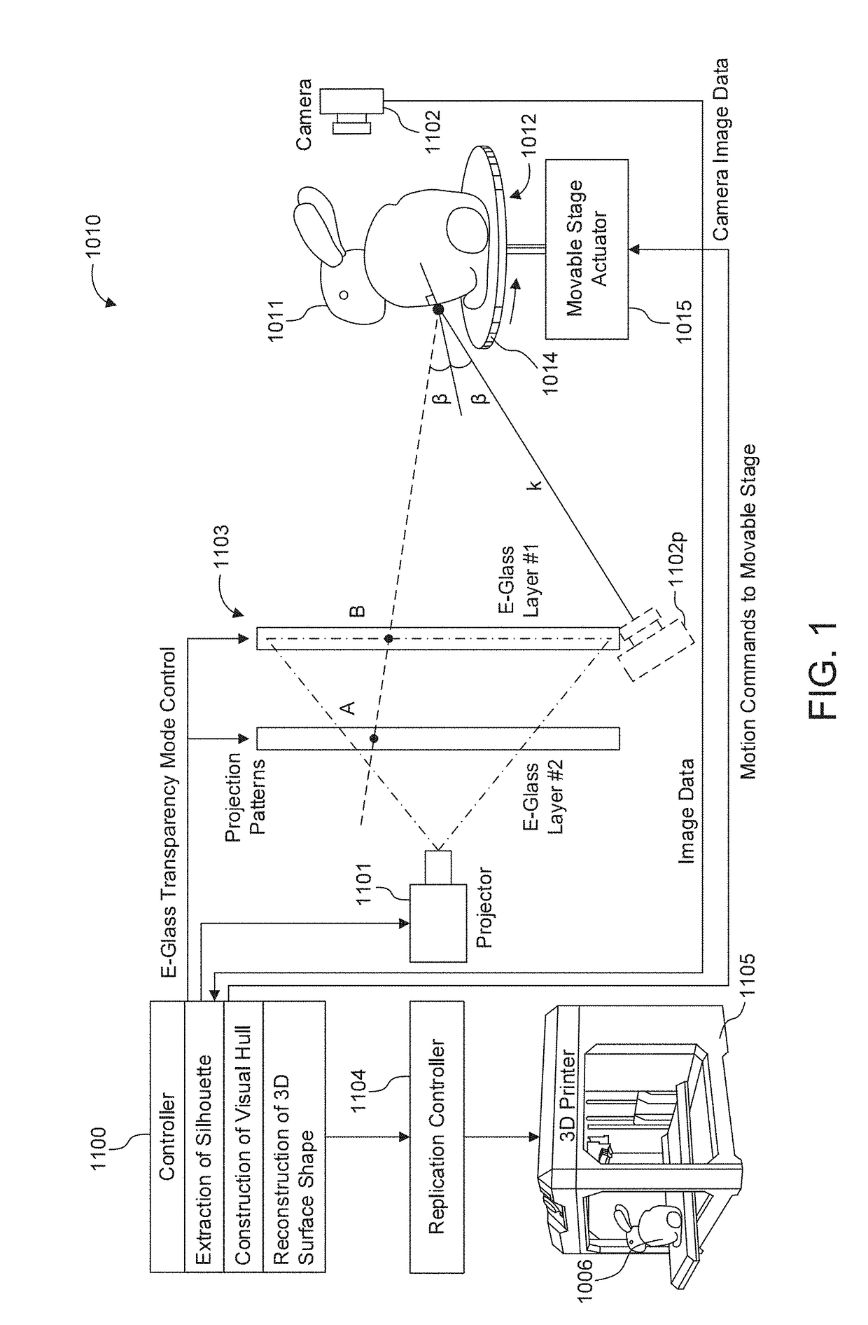
[0155] Object with diffuse surface (FIG. 8B): When a light ray hits this type of object, its intensity is reflected in many directions and might never hit the diffuse screen, creating a shadow. In this case, the spot B is dark.

case 2

[0156] Object with specular surface (FIG. 8C): When a light ray hits a specular surface, its intensity is entirely reflected in one direction which depends on the normal of the object's surface at the intersection point. The light does not reach the diffuse screen, and in this case the spot B is dark.

case 3

[0157] Transparent object (FIG. 8D): When a light ray hits a transparent object, its intensity is partially reflected (this part will never reach the diffuse screen) and partially goes through the object following a deflected path. The light ray rB might eventually hit the screen but at a point B′ instead of B, and with an intensity which is usually lower than the original intensity.

[0158]FIGS. 9A, 9B, 9A and 9B show examples of this case 3, for transparent objects. These figures show examples of shadows of two different but fully transparent objects when the projector projects flat light and a pattern consisting of vertical stripes. In FIGS. 9A and 9B, the object is a pyramid at two different orientations (here, rotation orientations). Likewise, in FIGS. 10A and 10B, the object is a cube at two different orientations (rotations). It can be observed in these figures that the vertically-striped pattern is deformed by the transparent object due to the deflected light rays.

Reconstructi...


PUM

PropertyMeasurementUnit
sizeaaaaaaaaaa
transparencyaaaaaaaaaa
transparentaaaaaaaaaa

Abstract

Shape measurement of a specular object even in the presence of multiple intra-object reflections such as those at concave regions of the object. Silhouettes of the object are extracted, by positioning the object between a camera and a background. A visual hull of the object is reconstructed based on the extracted silhouettes, such as by image capture of shadows of the object projected onto a screen, and image capture of reflections by the surface of the object of coded patterns onto the screen. The visual hull is used to distinguish between direct (single) reflections of the coded patterns at the surface of the object and multiple reflections. Only the direct (single) reflections are used to triangulate camera rays and light rays onto the surface of the object, with multiple reflections being excluded. The 3D surface shape may be derived by voxel carving of the visual hull, in which voxels along the light path of direct reflections are eliminated. For surface reconstruction of heterogeneous objects, which exhibit both diffuse and specular reflectivity, variations in the polarization state of polarized light may be used to separate between a diffuse component of reflection and a specular component.

Description

CROSS REFERENCE TO RELATED APPLICATIONS[0001]This application claims benefit of priority from the following U.S. provisional applications, the contents of all of which are incorporated by reference as if set forth here in full: U.S. Provisional Application No. 62 / 323,531 filed Apr. 15, 2016 (Attorney Docket 03650.020222.PV); U.S. Provisional Application No. 62 / 361,415 filed Jul. 12, 2016 (Attorney Docket 03650.020234.PV); U.S. Provisional Application No. 62 / 367,591 filed Jul. 27, 2016 (Attorney Docket 03650.020599.PV); U.S. Provisional Application No. 62 / 367,600 filed Jul. 27, 2016 (Attorney Docket 03650.020601.PV).FIELD[0002]The present disclosure relates to silhouette extraction and shape reconstruction of physical objects using multiple electronically-controllable light diffusing layers, and is particularly well-suited for shape reconstruction of specular and diffuse objects in the presence of multiple intra-object reflections.RELATED ART[0003]3D reconstruction of a specular obje...

Claims


Application Information

Patent Timeline
Patent Type & Authority Applications(United States)
IPC IPC(8): H04N13/00G06K9/46G02F1/1347H04N13/02G06T7/60H04N13/122G06V10/147G06V10/46
CPCH04N13/0018G06K9/4604G06T7/60G02F2203/03G02F1/13476G02F2203/01H04N13/0207G02F1/13306G03B15/06G03B17/54G03B21/00G03B21/62G03B37/02G03B2215/05G06T2207/10152G06T7/514G06T7/521H04N2013/0092H04N13/254H04N13/363H04N13/122G06V10/147G06V10/46H04N13/207
Inventor MARTINELLO, MANUELNEZAMABADI, MAHDILEVINE, EVAN
Owner CANON KK
Learn More