
Method, device and system for hydrodynamic flow focusing

a technology of hydrodynamic flow and focusing device, which is applied in the field of flow cytometry, can solve the problems of limited depth of focus, unsatisfactory throughput, and limited analysis and sorting capabilities of microfluidic systems

Inactive Publication Date: 2017-10-19
FOSS ANALYTICAL AS
View PDF3 Cites 10 Cited by
  • Summary
  • Abstract
  • Description
  • Claims
  • Application Information

AI Technical Summary

Benefits of technology

The present invention is a microfluidic system that uses a thin sheet to focus microparticles. The system is designed to allow for high-speed inspection and sorting of microparticles using high NA objectives. The microparticles can be observed easily when using a microscope or other optical instruments. The system includes a first and a second sheath flow inlet channel, which allows for normal optical force to the substrate plates, which can be used for optical sorting of microscopic objects. The technical effects of this invention include improved accuracy and efficiency in identifying and manipulating microparticles, resulting in improved precision and speed in various fields such as medical diagnostics and biological research.

Problems solved by technology

The depth of focus is also limited.
The throughput becomes unsatisfactory.
However, compared with the established instruments the microfluidic systems have so far only offered limited analysis and sorting capabilities.
The main obstacle has been the fact that the design of the flow cell of the established instruments is not readily transferable into the microfluidic flow cell fabrication technology.
In microfluidic systems it is difficult to fabricate a circular nozzle inside a coaxial tube.
Due to the built up construction of substrates a microfluidic system 2D hydrodynamic focusing is much more challenging.
Although an intuitive and seemingly sound design, it was quite demanding in fabrication requiring clean room processing of silicon substrates with tight tolerances.
The design with sharp angles is susceptible to sedimentation of microparticles fouling the microfluidic system as well as blow down of the sample fluid.
Due the protruding nozzle in the center of the larger channel the design is also susceptible to catching air bubbles which will be stuck on the front side of the nozzle.
Occurrence of air bubbles is a common source of fouling of microfluidic systems.
Microfluidic systems, which are susceptible to fouling by air bubbles, are not robust in large-scale use beyond the prototypes.
The complexity of manufacturing is significantly increased since the SU-8 polymer substrate required the use of complex, non-standard lithography in several steps.
The realized substrate cannot be fabricated using polymer microinjection molding or using standard lithography.
The design also features prominent voids and sharp angles which are susceptible to fouling the microfluidic system by air bubbles and microparticle sedimentation.
The design holds many sharp angles and tight confinement of the channels leading to the susceptibility to fouling by sedimentation.
Due to the complex interaction of laminar flow gradients and solid microparticles the performance achieved by focusing dyes cannot be expected to be reproduced with microparticles in the complex network of channels realized.
Thus, the demonstrated microfluidic system does not present a new, extendable focusing principle or design but simply the combination of known technology.
Four or five flow pumps result in a considerable hardware expense and add to the complexity in terms of many fluidic interconnections and more electronics.
The microfluidic system achieves 2D focusing of the sample to a sheet rather than a file, but the formation of a sheet is an unintentional and unutilized artefact of the microfluidic system.
The consequence of this is that there is an increased risk of coincidental events in the photomultiplier detector.
It would not be possible to mount a high NA objective for optical inspection from the side due to the short working distances of high NA objective compared with the available minimal distance.
For high quality microscope imaging the bonded interfaces of the substrates would intersect the optical light rendering high resolution diffraction limited impossible.

Method used


Image

  • Method, device and system for hydrodynamic flow focusing
  • Method, device and system for hydrodynamic flow focusing
  • Method, device and system for hydrodynamic flow focusing

Examples


Embodiment Construction

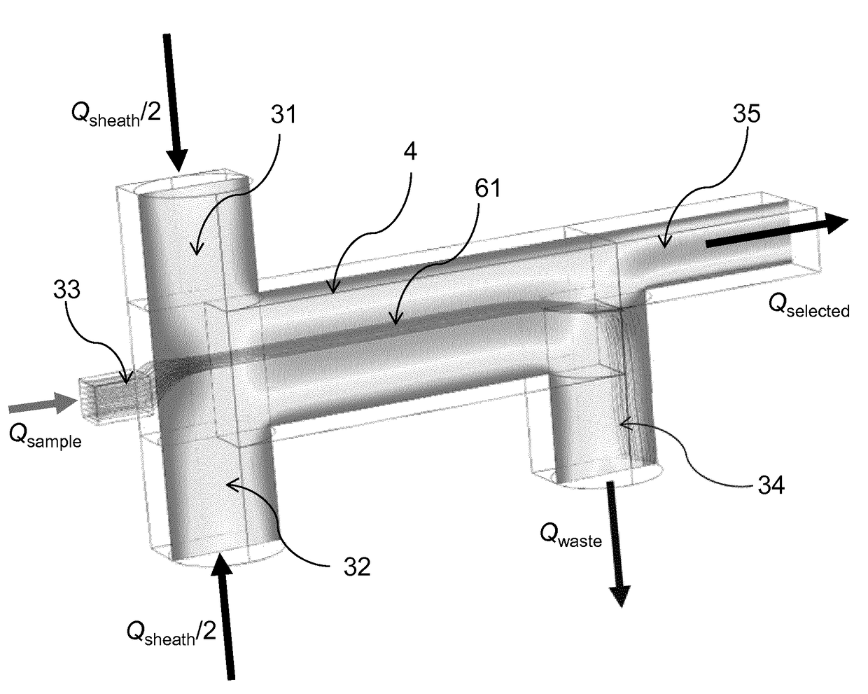
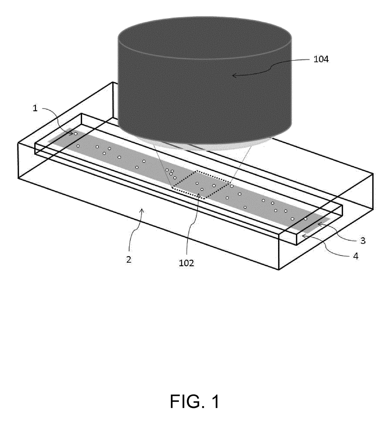
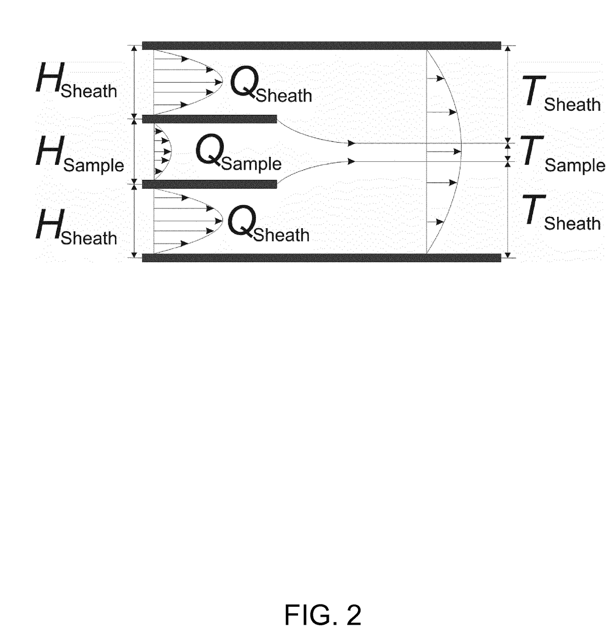
[0079]Referring to the above recitation of the method, apparatus and system of the first, second, third and fourth aspects of the invention, further features of embodiments of the invention will now be described. The optical objective may be arranged to provide a view onto the sample fluid at the inspection zone in a viewing direction which is perpendicular to the common flow direction, and the planar flow of the sample fluid may have a height in said viewing direction, which is smaller than or equal to a depth of focus of the optical objective. Flows of the first and second sheaths fluids may form planar inlets to said inspection zone, each of said planar inlets being preferably wider in a direction perpendicular to the common flow direction than the width of the inspection zone when seen in the plane of each respective planar inlet. The sample fluid and the first and second sheath fluids may be conveyed at a common flow velocity in said common flow direction at the inspection zone...


PUM


Abstract

In a method for hydrodynamic focusing of a laminar and planar sample fluid flow, a system is provided for analysis and / or sorting of microscopic objects in the sample fluid comprising an optical objective for optical inspection of the microscopic objects. Microscopic objects are conveyed in the laminar flow of the sample fluid, and two laminar and planar flow of sheath fluids are provided. The flow of the sample fluid is hydrodynamically focused at an optical inspection zone of the system by the sheath fluids. Focusing of the flow of the sample fluid is controlled such that all of the microscopic objects in the sample fluid are caused to be conveyed in a common flow direction in one single plane at the inspection zone of the system, and the microscopic objects in the fluid are optically inspected through the optical objective.

Description

CROSS-REFERENCE TO RELATED APPLICATIONS[0001]This application is the U.S. National Phase application of PCT Application No. PCT / EP2015 / 072545 filed on Sep. 30, 2015, which claims priority to European Patent Application No. 14187095.6 filed on Sep. 30, 2014 the entire contents of each of which are incorporated herein by reference.FIELD OF THE INVENTION[0002]The present invention relates to the field of flow cytometry. Specifically, it relates to the field of hydrodynamic flow focusing and to the structure of a flow cell (referred to as a hydrodynamic flow focusing devices) and its use in optical analysis or optical laser sorting of biological cells and microparticles (referred to as microscopic objects). The flow cell may be embodied as a microfluidic flow cell.BACKGROUND OF THE INVENTIONIntroduction[0003]In biotechnology, clinical diagnostics, and research there is a need to study and sort biological cells on an individual basis and this can be done with instruments capable of flow ...

Claims


Application Information

Patent Timeline
IPC IPC(8): G01N15/14B01L3/00G01N15/00G01N15/10
CPCG01N15/1404G01N15/1484B01L3/502776B01L3/502761B01L3/502746G01N2015/0065B01L2200/0636G01N2015/1413G01N2015/149B01L2200/0652B01L2400/082B01L2300/0654B01L2300/0864G01N2015/1006G01N15/147B01L2400/0454G01N2015/1415G01N15/01G01N15/149
Inventor RINDORF, LARS HENNINGGLUCKSTAD, JESPERAABO, THOMAS
Owner FOSS ANALYTICAL AS
Learn More