Quantum interference device, atomic oscillator, electronic apparatus, and vehicle
a technology of atomic oscillators and interference devices, applied in electrical apparatus, oscillator generators, pulse automatic control, etc., can solve problems such as difficulty in height reduction, and achieve the effect of height reduction
- Summary
- Abstract
- Description
- Claims
- Application Information
AI Technical Summary
Benefits of technology
Problems solved by technology
Method used
Image
Examples
first embodiment
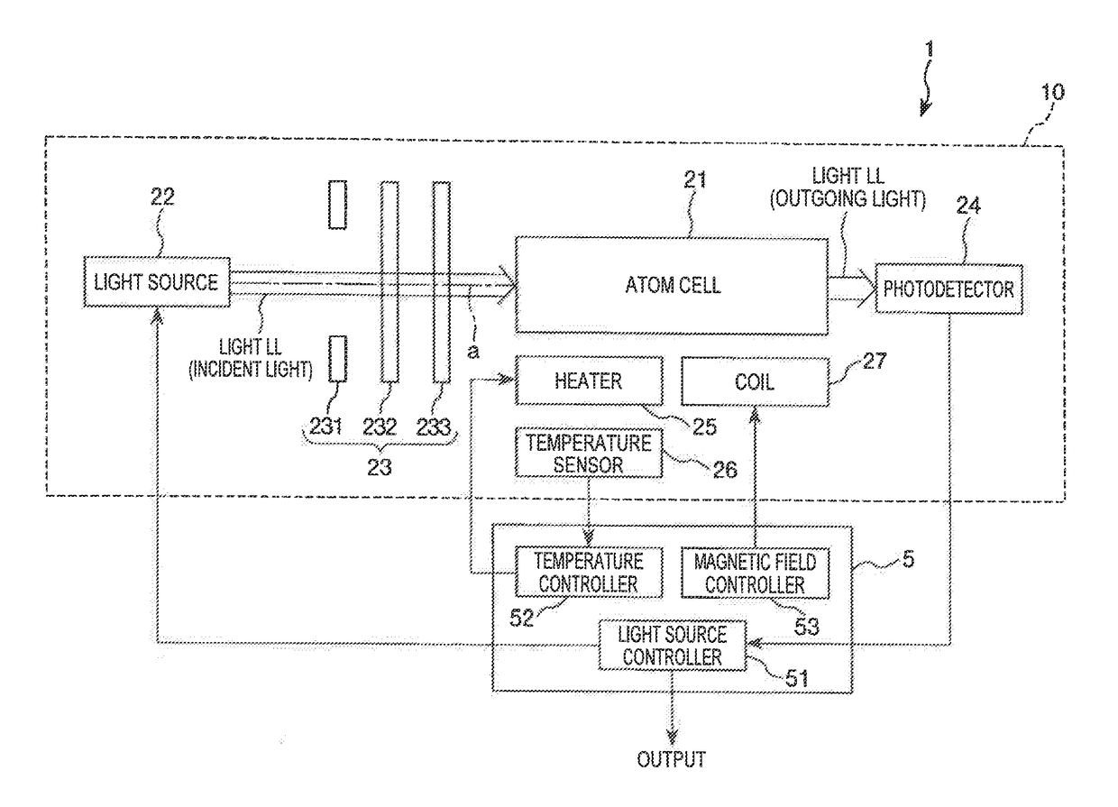
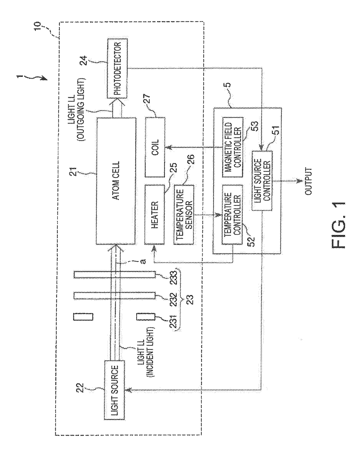
[0044]FIG. 1 is a cross-sectional view showing the atomic oscillator according to a first embodiment of the invention.
[0045]The atomic oscillator 1 shown in FIG. 1 is an atomic oscillator using the quantum interference effect (coherent population trapping (CPT)) with which there occurs a phenomenon that when irradiating an alkali metal atom with two resonance light beams having specific wavelengths different from each other at the same time, the two resonance light beams are transmitted through the alkali metal without being absorbed by the alkali metal. It should be noted that the phenomenon due to the quantum interference effect is also referred to as electromagnetically induced transparence (EIT) phenomenon.
[0046]As shown in FIG. 1, the atomic oscillator 1 has a package 10 for causing the quantum interference effect, and a controller 5 for controlling the package 10. Here, the package 10 has an atom cell 21, a light source 22, an optical system 23, a photodetector 24, a heater 25...
second embodiment
[0115]Then, a second embodiment of the invention will be described.
[0116]FIG. 5 is a cross-sectional view showing a schematic configuration of a package provided to an atomic oscillator according to the second embodiment of the invention. FIG. 6 is a plan view showing a support provided to the package shown in FIG. 5.
[0117]The atomic oscillator according to the present embodiment is substantially the same as the first embodiment described above except the point that the configuration of the support is different.
[0118]It should be noted that in the description below, the second embodiment will be described with a focus on the difference from the embodiment described above, and the description of substantially the same issues will be omitted. Further, in FIG. 5 and FIG. 6, the constituents substantially identical to those of the embodiment described above are denoted by the same reference symbols.
[0119]The package 10A provided to the atomic oscillator 1A shown in FIG. 5 is provided wi...
third embodiment
[0129]Then, a third embodiment of the invention will be described.
[0130]FIG. 7 is a cross-sectional view showing a schematic configuration of a package provided to an atomic oscillator according to the third embodiment of the invention.
[0131]The atomic oscillator according to the present embodiment is substantially the same as the first embodiment described above except the point that the arrangement of the coil is different.
[0132]It should be noted that in the description below, the third embodiment will be described with a focus on the difference from the embodiments described above, and the description of substantially the same issues will be omitted. Further, in FIG. 7, the constituents substantially identical to those of the embodiments described above are denoted by the same reference symbols.
[0133]The package 10B provided to the atomic oscillator 1B shown in FIG. 7 is provided with a coil 27B disposed outside the container 3 instead of the coil 27 in the first embodiment desc...
PUM
 Abstract
Description
Claims
Application Information
 - R&D
- Intellectual Property
- Life Sciences
- Materials
- Tech Scout
- Unparalleled Data Quality
- Higher Quality Content
- 60% Fewer Hallucinations
Browse by: Latest US Patents, China's latest patents, Technical Efficacy Thesaurus, Application Domain, Technology Topic, Popular Technical Reports.
© 2025 PatSnap. All rights reserved.Legal|Privacy policy|Modern Slavery Act Transparency Statement|Sitemap|About US| Contact US: help@patsnap.com


